
User's Manual
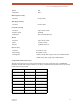
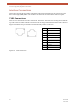

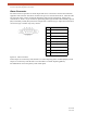

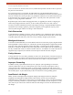
Table Of Contents
- EX-i Series GigE (FDD)
- Digital Microwave Radios
- Installation and Management Guide
- Legal Notice
- Open-Source License Information
- Table of Contents
- List of Figures
- List of Tables
- About this Document
- Introduction
- Pre-installation Tasks
- System Installation and Initiation Process
- Installation
- Configuration and Management
- Command Line Interface (CLI)
- Telnet into the Command Line Interface (CLI)
- Exalt Graphical User Interface (GUI)
- Quick Start
- Navigating the GUI
- Radio Information Page
- Administration Settings Page
- NTP and Time Zone Configurations
- Simple Network Management Protocol (SNMP) Configuration
- File Transfer Page
- File Activation Page
- System Configuration Page
- Allocation Page
- Ethernet Interface Configuration Page
- T1/E1 Configuration Pages
- MHS Configuration Page
- VLAN Configuration Page
- Ethernet Rate Limiting Page
- Ethernet Learning Page
- Syslog Configuration Page
- Ethernet Aggregation
- Cross Connect (X Connect) Page
- Alarms Page
- MHS Status Page
- Performance Page
- ATPC Statistics Page
- Event Log Page
- User Throughput Page
- Diagnostic Charts Page
- Ethernet Utilization Page
- PA Control Page
- Spectrum Analyzer
- Reboot Page
- Manual Page
- Specifications
- Interface Connections
- Troubleshooting
- Back-to-back Bench Testing
- General Compliance and Safety
- Safety Notices
- Regulatory Notices
- Regulatory Compliance
- EIRP Limits for the United States and Canada
- Licensing 6 and 11GHz Models
- Antennas 5GHz Models
- Copyright Notices
- END USER AGREEMENT
- Index

Exalt Installation and Management Guide
EX-i Series GigE (FDD) Digital Microwave Radios
202675-008 95
2016-06-01
Ethernet Connections
There are two orientations of Ethernet connections. ETH1 has the securing tab towards the top of the
connector while ETH2 has the securing tab towards the bottom of the connector. Figure 62 illustrates
the pin orientation and functionality of these connectors.
Figure 62 Ethernet connectors (ETH1 and ETH2)
The Ethernet connections implement Auto-MDIX, and therefore either ‘straight’ or ‘crossover’
Ethernet cables can be used, independent of the wiring of the connected device.
Pin Function
1 Paired with Pin 2
2 Paired with Pin 1
3 Paired with Pin 6
4 Paired with Pin 5
5 Paired with Pin 4
6 Paired with Pin 3
7 Paired with Pin 8
8 Paired with Pin 7