
Manual

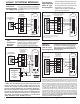


Table Of Contents

EWC Controls Inc. 385 Highway 33 Englishtown, NJ 07726 800-446-3110 FAX 732-446-5362 E-Mail- info@ewccontrols.com
14
SYSTEM WIRING CONTINUED - Specialty Applications
Variable Speed
AIR HANDLER
with 1 or 2 stage Heat
AND
DEHUMIDIFICATION
CAPABILITY
1 or 2 STAGE
HEAT PUMP
UZC4
W2
W1
RH
RC
Y2
O
Y1
G
RC/RH
LINK
B
E
H
V
A
C
-
S
Y
S
T
E
M
W
O
Y1
C
R
Y2
NC
NO
C
A
U
X
R
L
Y
W1
Y1
C
R
O
W2
Y2
G
DH
HUM
Wiring for typical 3 stage Heat,2stage cool Heat Pump. Diagram reflects De-humidification
terminal wired to the Auxiliary input. Auxiliary Relay Dip Switch #5, Bank #2, should be set
to (RA) Reverse Acting. Contact EWC Controls Technical support or visit our web site for
additional diagrams and alternate control methods to achieve De-humidification.
Using the UZC4’s Auxiliary Feature to control Dehumidify Operations
The Auxiliary Feature
can be used to
activate DeHumidify
Operations on
Variable or Constant
Speed HVAC Systems.
The UZC4 can be set up
to control DeHumidify
operations on most any
H e a t P u m p o r
Conventional HVAC
system. The UZC4 will
also activate a unique
Dehum idify Con tro l
Algorithm when the De-
humidify demand is
d e t e c t e d . W h e n a
separate control calls for
Dehumidification, the
UZC4 will activate “Y1”,
“G” and the Auxiliary
Relay, to signal the Air
Handler to slow the fan
down.
The UZC4 WILL ALSO
e n e r g i z e t h e ( E )
E m e r g e n c y o u t p u t
terminal to REHEAT the
cold discharge air and
Rapidly Dehumidify the
home. Energizing the
“E” during this cycle
prevents over-cooling
the home. A common
Customer complaint with
the DeHumidify cycle in
these HVAC systems.
NOTE1: The UZC4 will
n o t a c t i v a t e
dehumidify operations
unless the “Y1” (cool)
signal is also detected
at Zone 1.
NOTE2: A cooling or
h e a t i n g d e m a n d
detected at any other
zone can cause a delay
to activate or will
ter minat e the De-
Humidify operations.
NOTE3: Dehumidify can
only be achieved In (RA)
Reverse acting mode.
DHUM
G
R
O/W2
C
THERMIDISTAT
3 Heat 2 Cool HEAT PUMP
CONFIGURATION
C
W2
Y1
R
G
O/B
ONE
ZONE
ZONE 1
T'STAT
W1/E
Y2
AUX R
CO2
CO2
Carrier Bryant
R
W / W1
Y / Y2
Y1 / W2
R
Wiring for typical 4 stage Heat,2 stage cool Heat Pump. Diagram reflects De-humidification
terminal wired to the Auxiliary output (NC) Normally Closed terminal. Auxiliary Relay Dip
Switch #5, Bank #2, should be set to (RA) Reverse Acting when using the type of control
shown below.
This type of control uses (RA) reverse acting
logic to signal De-humidify demands.
Figure 21.
Figure 22.