
Overview of Primary Product
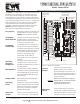
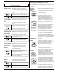
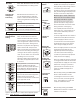
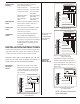
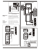
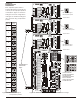
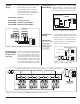
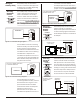
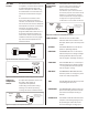
Table Of Contents

EWC Controls Inc. 385 Highway 33 Englishtown, NJ 07726 800-446-3110 FAX 732-635-8646 E-Mail- info@ewccontrols.com
9
A
U
X
I
L
L
A
R
Y
M1
M2
M2
NO
GND
GND
NC
RH
SNR
RH OUT
COM
+5+5
COM
CUT FOR
RH SENSOR
ND/URD Damper
Motor Wiring
Figure 17. Humidifier wiring diagram.
Figure 18. Humidistat wiring diagram.
Figure 19. Humidity sensor wiring diagram.
Figure 20. A combustion air damper.
Figure 21. A fresh air damper.
The Auxiliary relay can be used to
control a combustion damper, fresh
air damper or humidifier depending
on the DIP switch settings.
The auxiliary relay contacts can be
used to activate a humidifier using
either a humidistat or a humidity
sensor. In either case the humidifier
will be connected to the COM and
NO terminals. The M2-COM jumper on
the panel should be cut to isolate the
panel voltage from the humidifier
The auxiliary relay contacts can be
used to activate a combustion
damper that opens whenever there is
a call for heating. Figure 20 illustrates
an ND damper used as a combustion
air damper.
The auxiliary relay contacts can be
used to activate a fresh air damper
that opens for 0 to 32 minutes every
hour. The fresh air control will attempt
to fulfil the fresh air requirement during
heating or cooling calls. It will activate
the fan and open the damper at the
end of the hour only if the total fresh
air minutes have not been satisfied.
If a humidistat is used for monitoring
relative humidity, it should be wired as
shown in figure 18. The panel will
activate the humidifier whenever the
humidistat contacts close indicating
humidification is required. The
humidifier will operate a minimum of
10 minutes or until the humidistat has
been satisfied. The potentiometer on
the panel has no effect.
If a humidity sensor is used for
monitoring relative humidity, it should
be wired as shown in figure 19. The
panel will activate the humidifier
whenever the relative humidity rises
above the level set on the
potentiometer on the panel. The
humidifier will operate a minimum of
10 minutes or until the relative
humidity drops below the level set on
the potentiometer. Cut the RH SENSOR
jumper on the panel.
Wiring the
Auxiliary Relay
Selecting
Humidifier
Control
ON
ON
ON ON
ON
ON
6
6
6 7
7
7
OFF
OFF
OFF
OFF
OFF
OFF
ON
ON
ON
ON
ON
ON
AUXRLYB
AUXRLYB
AUXRLYB
AUXRLYA
AUXRLYA
AUXRLYA
Selecting
Combustion
Damper
Control
Selecting
Fresh Air
Control
A
U
X
I
L
L
A
R
Y
M1
M2
M2
NO
NC
COM
COM
HUMIDIFIER
CUT JUMPER WHEN USING A
HUMIDITY SENSOR ONLY.
DO NOT CUT JUMPER
DO NOT CUT JUMPER
NORMALLY CLOSED
SPRING RETURN
DAMPER
HUMIDITY
SENSOR
GND
RH
SNR
+5
CUT FOR
RH SENSOR
HUMIDISTAT
DO NOT CUT JUMPER WHEN USING
A STANDARD HUMIDISTAT.
0
25
35
16
45
55
32
HUMIDIFIER
FA MIN/HR
A
U
X
I
L
L
A
R
Y
M1
M2
M2
M4
M6
COM
COM
1
4
6
Spring Return
Motor wiring
MA-SR