
Overview of Primary Product
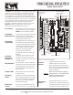
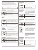
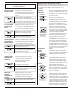
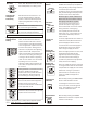
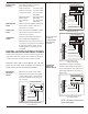
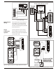
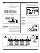
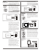
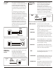
Table Of Contents

10:30
AM
68
Cool
Mo
10:30
AM
68
Cool
Mo
COOL OFF HEAT EM. HEAT ON AUTO
FAN
EWC Controls Inc. 385 Highway 33 Englishtown, NJ 07726 800-446-3110 FAX 732-635-8646 E-Mail- info@ewccontrols.com
6
Figure 7. Typical two-stage heat-cool
thermostat wiring.
W2 Y2 G Y1W1 C R
TSTAT 2
ZONE THERMOSTAT
W2
Y2
G
W1
C
Y1
R
On the UZC3 panel, the fan (G), the
compressor (Y1) and the reversing
valve (O/B) are powered by the RC
terminal. The heating (W1) is powered
by the RH terminal.
Typical gas/electric system wiring
using a single transformer is shown
below. A jumper wire is provided that
connects RC to RH.
HVAC System
Wiring
Single
Transformer
Systems
COMPRESSOR 2
RELAY
COMPRESSOR 1
RELAY
FAN RELAY
OUTDOOR UNIT
FURNACE
TERMINAL BOARD
GAS VALVE 2
GAS VALVE 1
TRANSFORMER
C Y2 Y1
G
W2
W1
R
Figure 8. Single transformer, 2-stage, gas/electric system.
RH
S
Y
S
T
E
M
RC
W1
RC
RH
W2
EM
G
B
O
W3
Y2
Y1
RH
W1
RH
S
Y
S
T
E
M
RC
G
RC
Y1
EM
B
W2
O
Y2
W3
COMPRESSOR
RELAY
FAN RELAY
OUTDOOR UNIT
MAY BE DIFFERENT COLOR
LEAD WIRES INSTEAD OF
LETTERED TERMINALS
OIL
BURNER
PRIMARY
CONTROL
CIRCULATOR
RELAY OR HOT
WATER VALVE
TRANSFORMER
C
T
G
R
T
Figure 10. Two-transformer oil burner with electric cooling.
Be sure to cut RC-RH
jumper for all dual
transformer systems
C
Figure 9. Dual Fuel Heat Pump w/Outside Air lock-out.
X
O
Y
C
R
W2
W1
Y
G
C
R
B R W
30 DEG. F. SPDT
OUTSIDE AIR
T’STAT
RH
S
Y
S
T
E
M
RC
W1
RC
RH
W2
EM
G
B
O
W3
Y2
Y1
UZC-3C
GAS
FAU
2 STAGE
HEAT PUMP
1 STAGE
DUAL FUEL SET-UP w/OAT