
Overview of Primary Product
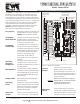
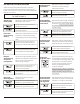
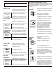
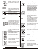
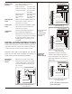
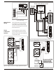
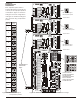
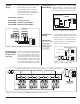
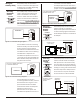
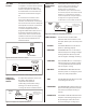
Table Of Contents

When the supply air sensor is used, the
cooling potentiometer sets the lowest
temperature the supply air can reach,
before the cooling is cycled off to
prevent indoor coil freeze-up. This
gives you additional equipment
protection.
The on board Emergency Heat switch
disables the heat pump compressor
during heating calls(cooling calls are
not affected) and activates
emergency heat, second stage heat
(W2), and third stage heat (W3), when
the switch is set to the ON position.
Should only be used if a heat/cool
thermostat is used in Zone1 with a
heat pump or dual fuel system.
The One Zone switch allows you to
operate the system using only the
Zone1 thermostat. This can be useful
during vacation or during long
unoccupied periods. All zones will
respond to zone 1 thermostat only. It
can also be initiated by a remote
switch or timer.
Momentarily pressing the TIMER RESET
button clears the built-in timers
controlling the minimum run timer,
short cycle timer, and changeover
timer. This enables you to test and
certify the installation faster.
Momentarily pressing the SYSTEM
RESET button resets the computer and
initiates a new start up.
35
40 45
50
COOLING
LIMIT
Setting the
Cooling Limit
Emergency Heat
Switch
One Zone
Switch
TIMER
RESET
Timer Reset
BUTTON
SYSTEM
RESET
System Reset
BUTTON
EM HEAT
ONE ZONE
ON
ONE
OFF
ALL
110
120
130
140
150
160
170
HEATING
LIMIT
DIP switch 8 selects either a 5 or 10-
minute delay before the opposite
system can be activated to prevent
rapid cycling between heating and
cooling.
Switches 2, 3 and 4 on the OP SYS TMR
bank, set the maximum call time
before the UZC3 switches to service
zones calling for the opposing system,
even though there may be more calls
for the active system. Setting all the
switches to 0 (ON) turns the opposing
system feature OFF. The panel will
service zones based on whether there
are more zones calling for heating or
cooling. It will not switch to opposing
calls. You can select 10 to 60 minutes
by setting one or more of the
switches to OFF. If all the switches are
set to OFF, the opposite system timer
is one hour.
A factory supplied 10K ohm resistor is
installed in the SA1/SA2 terminals. An
optional Supply air Sensor can be
connected to monitor the supply air
temperatures. Remove the resistor
when using the supply air sensor.
When the supply air sensor is used, the
heating potentiometer sets the
highest temperature the supply air
can reach, before the heating is
cycled off to prevent the equipment
safety sensors from tripping.
Figure 2. DIP switches 2, 3 and 4 set the opposite system
timer. NOTE: DIP switch 1 , on this bank is not used.
Selecting the
Changeover
Time Delay
Setting Opposite
System Service
Timing
Setting the
Heating Limit
Set the switch to the ON position for a
5-minute changeover delay.
Set the switch to the OFF position for
a 10-minute changeover delay.
ONON
88
10
10
5
5
Setting switches 2, 3 and 4 to the ON
positions, disables the opposite
system service. The panel will service
zones based on whether there are
more heating or cooling calls only.
Setting switch 3 to OFF and switches 2
and 4 to ON, would set the opposite
system timer to 20 minutes of
continuous call before it would switch
to the opposite mode.
Setting switch 2 and 3 to OFF and
switch 4 to ON, would set the opposite
system timer to 30 minutes.
ONON ONON ONON
ON ON
ONONONON
444 333 212121
0
0
0
30
20
10
30
20
10
30
0
0
20
0
0
10
NOT USED
NOT USED
NOT USED
0
0
ONON
67
OFF
OFF
ON
ON
AUXRLYB
AUXRLYA
Auxillary Relay
Not Used
When both DIP switches are set to ON,
the Auxillary Relay is not being used.
EWC Controls Inc. 385 Highway 33 Englishtown, NJ 07726 800-446-3110 FAX 732-635-8646 E-Mail- info@ewccontrols.com
4
Supply air
Sensor
ON
NOT USED
OP SYS
TIMER
1 2 3 4
DIP SWITCH BANK “C”