
Overview of Primary Product
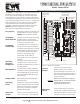
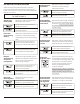
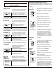
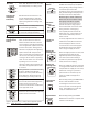
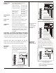
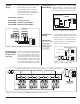
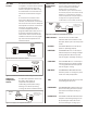
Table Of Contents

5
10
15
20
25
30
35
W2/Y2
TIMER
DIP switch 1 selects a gas/electric or
heat pump HVAC system.
DIP switch 5 selects a standard
Heat/Cool or Heat Pump type
thermostat for Zone1.
DIP switch 6 enables (YES) or disables
(NO), the panel's on board emergency
heat switch. The switch should always
be disabled if a heat pump thermostat
is used in Zone1.
DIP switch 7 selects whether stage 2
heating and cooling is controlled by 2
stage thermostats, or the W2/Y2 timer.
There are two 8-position DIP switch banks, and one 4-
position DIP switch bank that selects the options on the
UZC3. For the purpose of clarity we will call them Dip Switch
Bank “A”, “B”, and “C”.
DIP switch 8 selects whether any zone
thermostat can call for continuous fan
operation or, only Zone1 thermostat.
Second stage heating and cooling is
controlled by the amount of time stage
one has been continuously calling. The
potentiometer on the board sets the
amount of time first stage must call
before, second stage heating or
cooling is activated.
Stage 3 heating is always controlled by
the Timer and will be activated after
stage 2 has been calling for the time set
on the Timer.
Set the switch to the HC position for
heat/cool type thermostat.
Set the switch to the YES position to
enable the panel EM HEAT switch.
Set the switch to the TS position to
control stage 2 with thermostats.
Set the switch to the ANY position to
allow any zone thermostat to call for
continuous fan operation.
Set the switch to the HP position for
heat pump type thermostat.
Set the switch to the NO position to
disable the panel EM HEAT switch.
Set the switch to the TM position to
control stage 2 with the timer.
Set the switch to the Z1 position to
allow only Zone1 thermostat to call for
continuous fan operation.
Selecting Zone1
Thermostat
Enable/Disable
Panel Emergency
Heat Switch
Selecting Stage
Two and Three
Control
Selecting Which
Zones Can Call
for Continuous
Fan Operation
Setting the
Stage Two Timer
EWC Controls Inc. 385 Highway 33 Englishtown, NJ 07726 800-446-3110 FAX 732-635-8646 E-Mail- info@ewccontrols.com
2
ONONONON ONONONON
5678 5678
HP
NO
TM
TM
NO
Z1
Z1
HP
HC
YES
TS
TS
YES
ANY
ANY
HC
DIP switch 2 selects whether or not the
indoor fan is activated by the panel
during heating calls, as well as cooling
calls.
Set the switch to the EL position to
activate the fan during a heating or
cooling call. ( Electric Heat, Hydronic)
Set the switch to the GAS position to
activate the fan during a cooling call
only. (Gas/Electric, Heat Pumps)
Indoor Fan
Control During
Heating
ONON
22
EL
EL
GAS
GAS
Selecting the
HVAC System
Set the switch to the ON position for
gas/electric systems.
Set the switch to the OFF position for
heat pump systems.
ONON
11
HP
HP
GAS
GAS
DIP switch 4 selects O or B type
reversing valve.
Set the switch to the ON position to
enable for O type reversing valve .
Set the switch to the OFF position to
enable for B type reversing valve.
Heat Pump
Reversing Valve
ONON
44
B
B
O
O
DIP switch 3 selects whether all zone
dampers open during a continuous fan
call or, only the zones calling for
continuous fan will open.
Set the switch to the ZC position to
open only the zones calling for
continuous fan operation.
Set the switch to the ALL position to
open all dampers during continuous
fan operation.
Dampers
Opened During
Continuous
Fan Operation
ONON
33
ALL
ALL
ZC
ZC
DIP SWITCH SETTINGS/OPTIONS
DIP SWITCH BANK “A”