
Overview of Primary Product
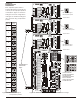
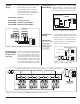
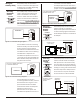
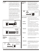
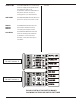
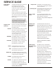
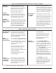
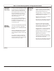
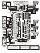
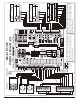
Table Of Contents

LEDs On But
System Not
Responding
LEDs and
System Not
Responding
Measuring
Thermostat
Voltages
Check the HVAC field wiring to insure it
is correct. Be sure all wires are secured
in the terminals. Check that there is
24VAC at the RC and RH terminals.
Use the HVAC system common (C) as
the ground lead of your meter. A
jumper is provided near the system
terminal block, to isolate for dual
transformer systems.
You can test the HVAC system by
shorting terminals R and W together to
activate the heater, RC to Y to
activate the compressor and RC to G
to activate the fan.
Check that the STATUS LED is blinking to
insure the computer is operating
properly. Press the SYSTEM RESET switch
if it is not.
Press the TMR RESET switch to clear the
timers that may be preventing the
call, changeover delay or short cycle
timers.
If the system still does not respond,
measure the voltage at each zone
thermostat terminal to insure they are
correct and a call is in order.
Heat/Cool thermostats will apply
24VAC to the W1 terminal during a
stage 1 heating call and W1 and W2
during a stage 2 heating call.
During a stage 1 cooling call, 24VAC
is applied to both Y1 and G, and to Y2
during a stage 2 cooling call.
During a continuous fan call, 24VAC is
applied to the G terminal.
Be sure the RC and RH terminals at the
thermostats are jumpered together.
Heat Pump thermostats will apply
24VAC to the Y1, B and G terminal
during a stage 1 heating call and W2
during a stage 2 heating call.
During a stage 1 cooling call, 24VAC
is applied to Y1, O and G and to Y2
during a stage 2 cooling call.
During a continuous fan call, 24VAC is
applied to the G terminal.
During an emergency heat call the
thermostat will normally apply 24VAC
to the EM and G terminals.
Be sure the RC and RH terminals at the
thermostats are jumpered together.
14
Table 3. Trouble Shooting Heating, Cooling and Fan Problems
EWC Controls Inc. 385 Highway 33 Englishtown, NJ 07726 800-446-3110 FAX 732-635-8646 E-Mail- info@ewccontrols.com
NOTES: