
Overview of Primary Product
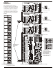
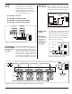
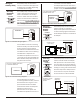
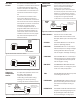
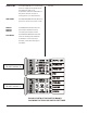
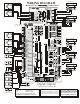
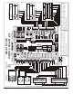
Table Of Contents

Damper LED On
But Damper Not
Responding
UZC3
Damper LED
Not Responding
UEX-22
Damper LED &
Damper Not
Responding
Testing a
Damper Motor
Check the damper wiring to insure it is
correctly wired. Be sure the wires are
secured in the terminals. Test the
damper motor to insure it is properly
operating. If the problem still persists,
call Technical Support.
Check that the STATUS LED is blinking. If
it is not, press the SYSTEM RESET switch.
Press the TMR RESET switch to clear any
timers that may be keeping the call
off and the damper from not
responding.
Check the voltage at each zone
thermostat terminals to insure the
damper should be activated.
Check that the dip switch options are
properly configured.
If the problem still persists. Call
Technical Support.
Check that the jumper cables are
installed properly.
Check the voltage at each zone
thermostat terminal to insure the
damper should be activated.
If the problem still persists, call
Technical Support.
If the damper is on an expansion
panel, check the DIP switch settings
on each expansion panel to insure
they are properly set. Check the 24
VAC power to insure the expansion
panel is powered.
For an RDN/SMDL/BMDL type
damper, connect 24VAC common
to terminal 1 and 24VAC to terminals
2 and 4. The damper should open.
Remove 24VAC from terminal 4 and
the damper should close.
For an SMD/BMD/IMD typedamper,
connect 24VAC common to
terminal 1 and 24VAC to terminal 4
and the damper should open.
Remove 24VAC from terminal 4 and
apply 24VAC to terminal 6 and the
damper should close. Be sure there
is a jumper between terminals 2 and
5.
For a URD/ND type damper,
connect 24 VAC common to
terminal 1 and 24 VAC to terminal 4.
The damper should open. Remove
24 VAC from terminal 4 and apply
24 VAC to terminal 6 and the
damper should close.
Table 2. Detecting Damper Problems
Detecting
24VAC Short
Detecting Loss
of +24VDC
or +5VDC
Isolating
24VAC Shorts
UZC3 or UEX-22
Panels
Isolating
24VAC Shorts
Panel or Wiring
The STATUS LED will be off, you will
measure 24VAC at the transformer
terminal 1& 2, but not at any damper
M1& M2 terminals or any zone
thermostat R & C terminals. The
thermal fuse will be very hot.
The +5VDC and +24VDC can be
measured at the test points. If either
voltage is not correct, disconnect the
jumper cable connecting the main
panel and the first expansion panel.
If the voltage problem disappears,
check that the 24VAC power is wired
to the correct terminals (terminal 1 to
1 and terminal 2 to 2 as shown in
figure 20). If the problem still persists,
call Technical Support.
Remove the power to the panel and
all expansion panels (if present) and
allow the fuse to cool. Disconnect the
jumper cable between the main
panel and the first expansion panel.
Re-power the panel. If the short
persists, call Technical Support.
Remove the wire at each zone
thermostat R terminal on the panel
and test, if the short still persists. If the
short disappears, check the zone
thermostat field wiring for shorts.
Disconnect all the wires at each
damper terminal block (M1, M2, M4 &
M6). If the short disappears, check the
damper field wiring and the damper
motors for shorts to ground. If the short
still persists, call Technical Support.
Table 1. Detecting 24VAC Shorts and Loss of +5VDC or +24VDC
EWC Controls Inc. 385 Highway 33 Englishtown, NJ 07726 800-446-3110 FAX 732-635-8646 E-Mail- info@ewccontrols.com
13
Call Technical Support @ 1-800-526-4048