
Overview of Primary Product
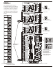
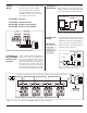
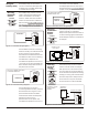
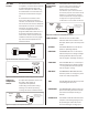
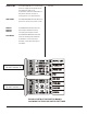
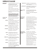
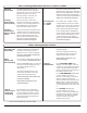
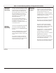
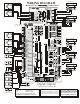
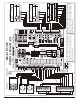
Table Of Contents

SERVICE GUIDE
Some Helpful
Guidelines
Using the LED
Indicators
STATUS
Check 24VAC
Power
Dampers Not
Responding
Properly
HVAC System
Not Responding
Properly
HEATING
COOLING
PURGE
SA LMT
EM HT
FAN
FRESH AIR
Damper LED
Aux Relay LED
Voltage measurements on the panel
at the damper terminals and
thermostat terminals, should be
made with the ground lead of your
meter on terminal 1 of the 24VAC
input terminals.
All VAC measurements at the HVAC
system terminals should be made with
the meter ground lead on the HVAC
system's C or common terminal at the
HVAC system.
Caution! The thermal fuse (F1) gets
very hot when a short occurs in the
24VAC wiring on the panel. Always use
caution when checking the fuse.
There are a number of LED indicators
that indicate the status of the panel
and HVAC system.
The STATUS LED blinks slowly to indicate
the microcomputer is operating
properly. If the LED is continuously off it
could indicate that the panel does
not have power or the
microcomputer needs to be reset.
You should measure 24VAC at all
damper M1& M2 terminals, and all
thermostat R & C terminals.
See Table 1 if any of these voltages are
not present.
If the Damper LED indicators are
responding properly, but the dampers
appear to be malfunctioning, check
that the dampers are wired correctly.
If the Damper LEDs are not
responding properly, check the calls
on each zone thermostat. If the calls
indicate a damper should be
activated and is not, press the TMR
RESET switch to reset any timers that
might be inhibiting a call.
Check that the DIP switch
options have been properly
selected.
If the HEAT, COOL and FAN LED
indicators are responding properly,
but the system appears to be
malfunctioning, check that the HVAC
system is wired correctly.
If the HEAT, COOL or FAN LED is not
responding properly, check the calls
on each zone thermostat. If the calls
indicate an HVAC call should be
activated and is not, press the TMR
RESET switch to reset the timers that
might be inhibiting a call.
Check that the option DIP switches
have been set properly.
If the problem persists, see Table 3.
The HEATING LED is on continuously
during stage1 heating and blinks
during stage 2 and 3 heating calls.
The COOLING LED is on continuously
during stage1 cooling and blinks
during stage 2 cooling calls.
The PURGE LED indicates that the
panel is in a purge cycle.
The supply air limit LED indicates that
the supply air temperature has
exceeded the high or low supply air
temperature limit. The LED blinks if the
sensor is open or shorted.
The EM HT LED indicates that the
emergency heat mode is active.
The FAN LED indicates that the panel
has turned the indoor fan on.
The FRESH AIR LED indicates that the
panel has activated the auxiliary relay
to open the fresh air damper.
The DMPR1, 2 and 3 LEDs indicate
that the relay controlling the damper
motor is activated.
The AUX RELAY LED indicates that the
fresh air damper, combustion air
damper or humidifier has been
activated.
12
EWC Controls Inc. 385 Highway 33 Englishtown, NJ 07726 800-446-3110 FAX 732-635-8646 E-Mail- info@ewccontrols.com