Configuration Manual Version 11.
CONFIGURATION MANUAL XT3 Server 11.02 Copyright EVS Broadcast Equipment S.A.– Copyright © 2011-2013. All rights reserved. Disclaimer The information in this manual is furnished for informational use only and subject to change without notice. While every effort has been made to ensure that the information contained in this user manual is accurate, up-to-date and reliable, EVS Broadcast Equipment cannot be held responsible for inaccuracies or errors that may appear in this publication.
EVS Broadcast Equipment S.A. Issue 11.02.A July 2013 Table of Contents TABLE OF CONTENTS II WHAT'S NEW? V 1. 1 INTRODUCTION 1.1. Introduction to the Configuration of EVS Servers 1 1.2. Introduction to the Manual 3 1.3. Starting the EVS Server 4 1.4. Accessing the Web-Based Interface 5 2. 6 MULTICAM SETUP 2.1. Overview of User Interfaces 6 2.1.2. Navigability and Commands 9 2.2. Configuration Lines 11 2.2.1. Chapter Contents 11 2.2.2. Launching a Configuration 11 2.2.3.
CONFIGURATION MANUAL XT3 Server 11.02 2.5.6. Exporting Log Files 3. MULTICAM CONFIGURATION 3.1. Overview on User Interfaces 44 44 3.1.1. Introduction 44 3.1.2. Overview of the Multicam Configuration Window 46 3.1.3. Navigating and Editing in the Multicam Configuration Window 49 3.1.4. Overview of the Setup Menus in the Remote Panel 51 3.1.5. Navigating and Editing in the Setup Menus of the Remote Panel 52 3.1.6. Required Application Reboot 54 3.2. Supported Configurations 55 3.2.1.
EVS Broadcast Equipment S.A. 3.8. GPI Tab 179 3.8.1. Overview 179 3.8.2. GPI Settings 180 3.8.3. Tally Settings 184 3.9. Operation Tab 186 3.9.1. Overview 186 3.9.2. OSD Settings 190 3.9.3. Audio Meters OSD Settings 192 3.9.4. Clips Settings 194 3.9.5. Playlist Settings 200 3.9.6. Timeline Settings 206 3.9.7. Protection Settings 207 3.9.8. Keywords Settings 209 3.9.9. Push Settings 211 3.9.10. Audio Settings 214 3.9.11. EVS Controller Settings 216 3.9.12.
CONFIGURATION MANUAL XT3 Server 11.02 What's New? This manual has not been subject to changes associated to new features in release 11.02. Further to the new EVS branding, the look and feel of the web-based interface has however been modified. For the same reason, the look and feel of the configuration manual has also been modified. In addition, some minor changes have been implemented.
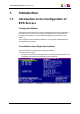
CONFIGURATION MANUAL XT3 Server 11.02 1. Introduction 1.1. Introduction to the Configuration of EVS Servers Configuration Module The Multicam Setup application is used for configuration and maintenance operations on EVS video servers. It is also used to select which application to run, since EVS disk recorders have the ability to run various dedicated applications (Video Server, Slow Motion, …). The configuration module available from Multicam 11.
EVS Broadcast Equipment S.A. • Issue 11.02.A July 2013 a configuration section for each configuration line. It is presented in seven tabs which easily give access to all configuration parameters: Simple User Interface The user interface is simple and clear thanks to: • the separation of basic and advanced parameters The most commonly used parameters are displayed in a basic mode while more specific parameters are hidden, and can be displayed when you toggle to the advanced mode.
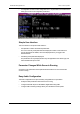
CONFIGURATION MANUAL XT3 Server 11.02 Configuration Available from Server, Web and Remote Panel You can configure the EVS server using one of the three available tools: • The server-based application (VGA) features all settings and commands for the setup and configuration. • The newly designed web-based interface is equivalent to the server-based application and enables engineers to configure the EVS server remotely.
EVS Broadcast Equipment S.A. Issue 11.02.A July 2013 Configuration Manual Structure The Server Configuration manual is organized in two sections: • • 1.3. A section dedicated to the Multicam Setup window that mainly features: ◦ the configurations lines and their management ◦ the functions related to server administration and maintenance.
CONFIGURATION MANUAL XT3 Server 11.02 1.4. Accessing the Web-Based Interface Prerequisite When the EVS server is started, you can access the web-based interface of the Multicam Setup application for that EVS server from any computer that is on the same network range as the EVS server. You can use any browser to open the web-based interface. Procedure To be able to open the web-based interface in a browser, you need to know the IP address of the PC LAN of the EVS server.
EVS Broadcast Equipment S.A. 2. Multicam Setup 2.1. Overview of User Interfaces 2.1.1. Overview of the Setup Areas Issue 11.02.A July 2013 General Description The Multicam Setup window is the window that opens first when the Multicam Setup application is launched. It is displayed when the EVS server is started but does not run a given configuration yet. The Multicam Setup window allows users to: • view and manage the various configuration lines.
CONFIGURATION MANUAL XT3 Server 11.02 The following screenshot presents the Multicam Setup window in the web-based interface: 2.
EVS Broadcast Equipment S.A. Issue 11.02.A July 2013 Description of the Areas The table below describes the various parts of Multicam Setup window: 8 # Name of area Description 1. Title bar The title bar displays the following information: • Multicam version • server facility name (if any) • chassis type • server serial number 2. Configuration Lines This area shows all configurations the EVS server can run: • 16 configurations lines are available on an EVS server.
CONFIGURATION MANUAL XT3 Server 11.02 2.1.2. # Name of area Description 5. Task bar The Task bar (Server-based application) displays commands for the main actions in the window. See section "Navigability and Commands" on page 9 for more information. 5'. Status bar The Status bar (web-based interface) displays: • the Multicam Setup application status • the date and time of the last refresh • the Refresh button 6.
EVS Broadcast Equipment S.A. Issue 11.02.A July 2013 Configuration Lines In the Configuration Lines area, a configuration line is highlighted when it is selected. The main commands for configuration line management are presented below: Command description Command key Moving up in the list of configuration lines UP ARROW Moving down in the list of configuration lines DOWN ARROW Starting the server with a given configuration line ENTER on selected line.
CONFIGURATION MANUAL XT3 Server 11.02 Tools Menu To call a Tools command, simply click on the command in the Tools menu. This will open the corresponding window. 2.2. Configuration Lines 2.2.1. Chapter Contents The table below presents the topics of this section and shows whether the feature described is available from the web-based interface and/or from the server-based interface. 2.2.2. Section Page Server-Based Web-Based "Launching a Configuration" 2.2.
EVS Broadcast Equipment S.A. Issue 11.02.A July 2013 In the Web-Based Interface To start a configuration in the web-based interface, click the Launch icon configuration line you want to launch. next to the Automatic Launch From the server-based application, it is possible to set the server so that the last used configuration line is automatically launched when the Multicam Setup window has stayed open for five seconds.
CONFIGURATION MANUAL XT3 Server 11.02 In the Server-Based Application To edit a configuration line in the server-based application, proceed as follows: 1. Press the UP ARROW or DOWN ARROW key to respectively move up and down in the list of configuration lines until the requested line is highlighted. 2. Press F8. The Configuration window opens. See section "Multicam Configuration" on page 44 to edit the configuration parameters. 3.
EVS Broadcast Equipment S.A. 2.2.4. Issue 11.02.A July 2013 Renaming Configuration Lines Introduction When the EVS server is delivered, default names are assigned to the configuration lines. You can change them as explained below. In the Server-Based Application To rename the configuration line in the server-based application, proceed as follows: 1. Press the UP ARROW or DOWN ARROW key to respectively move up and down in the list of configuration lines until the requested line is highlighted. 2.
CONFIGURATION MANUAL XT3 Server 11.02 2.2.5. Exporting and Importing Configuration Lines How to Export Configuration Lines Note The screenshots in this section features configuration names which are examples, and may not reflect configurations supported on your EVS server. In the Server-Based Application To export configuration lines from an EVS server in the server-based application, proceed as follows: 1. In the Multicam Setup window, press P to call the Export Configuration Lines command.
EVS Broadcast Equipment S.A. Issue 11.02.A July 2013 3. If requested, change the selection of configuration lines selected for export on the left pane: ◦ By default, a cross is displayed in front of all configuration lines, which means they are all selected for export. ◦ To deselect a line, use the UP ARROW or DOWN ARROW key to highlight the requested line, and press SPACEBAR. The cross is removed, and the deselected lines turn light gray. 4. Press TAB to shift the focus to the right pane. 5.
CONFIGURATION MANUAL XT3 Server 11.02 2. Click Export next to the configuration line you want to export. 3. In the File Download dialog box, click Save. 4. Select the location where you will save the export configuration file (.lin file) and, if requested, change the file name. 5. Click Save. The export file is saved at the requested location. If you want to export several configuration lines, repeat this operation for all requested configuration lines.
EVS Broadcast Equipment S.A. Issue 11.02.A July 2013 3. On the left pane, use the UP ARROW or DOWN ARROW key to highlight the folder that contains the configuration file you want to import. When the folder is selected, the right pane shows: ◦ a cross in front of the configuration lines that will be imported. The lines are imported onto the same position and with the same name as in the export file. 4. Press TAB to shift the focus to the right pane. 5.
CONFIGURATION MANUAL XT3 Server 11.02 In the Web-Based Interface Note In the web-based interface, it is only possible to import configuration lines one by one. To import configuration lines onto an EVS server in the web-based interface, proceed as follows: 1. From the Multicam Setup window, click Import configuration lines in the Tools menu. The Import configuration line window opens. 2. Click Select next to the top field and select the configuration file you want to import. 3.
EVS Broadcast Equipment S.A. 2.2.6. Issue 11.02.A July 2013 Changing the Position of Configuration Lines In the Server-Based Application To move a configuration line up in the list in the server-based application, proceed as follows: 1. Press the UP ARROW or DOWN ARROW key to respectively move up and down in the list of configuration lines until the requested line is highlighted. 2. Do one of the following: ◦ To move the selected line up, press CTRL + UP ARROW.
CONFIGURATION MANUAL XT3 Server 11.02 In the Web-Based Interface The feature to copy and paste configuration lines is not available as such in the webbased interface. You can however use the import and export feature to change the position of lines in the list of configuration lines. How to Delete Configuration Lines Warning When you delete a configuration line, the line will automatically be deleted, without prior warning message.
EVS Broadcast Equipment S.A. 2.3. Server Parameters 2.3.1. Chapter Contents Issue 11.02.A July 2013 The table below presents the topics of this section and shows whether the described features are available from the web-based interface and/or from the server-based interface. 2.3.2. Commands Page ServerBased WebBased "Assigning a Server Facility Name" 2.3.2 Yes Yes "Activating and Deactivating the Password Protection" 2.3.3 Yes No "Setting the Server LAN PC Address" 2.3.
CONFIGURATION MANUAL XT3 Server 11.02 In the Server-Based Application To assign a server facility name in the server-based application, proceed as follows: 1. In the Multicam Setup window, press F to call the Assign server facility name command. A dialog box opens: 2. Type the server facility name and press ENTER. The facility name is directly assigned and displayed in the Title bar, as well as on the OSD.
EVS Broadcast Equipment S.A. Issue 11.02.A July 2013 The password protection has the following impact on the various user interfaces: • The password is required to apply changes to configuration parameters in the serverbased application and in the web-based interface. • On the Remote Panel, the Technical Setup menu is not available. How to Activate the Password on the EVS Server To activate a password on the EVS server, proceed as follows: 1.
CONFIGURATION MANUAL XT3 Server 11.02 Deactivating the Password on the EVS Server Once the password protection is active, it can only be deactivated from the server-based application as follows: 1. In the Multicam Setup window, press W to call the Enable password command. A message opens to warn you that you are about to remove the password protection: 2. Press the RIGHT ARROW key to select 'Yes' and press ENTER 3.
EVS Broadcast Equipment S.A. Issue 11.02.A July 2013 Settings The MTPC board connection settings are described in the table below: Setting Description IP Address Specifies the IP address to connect to the port #1 of the MTPC board on the server. The IP addresses 0.0.0.0 and 255.255.255.255 are not allowed. Subnet Mask Specifies the range of logical addresses within the address space assigned to the MTPC board connection.
CONFIGURATION MANUAL XT3 Server 11.02 Supported Formats The supported date format is DD-MM-YYYY, as shown in the example below: • 15-03-2011 for March 15, 2011 The supported time format is hh:mm:ss, as shown in the example below • 22:58:00 for 22 h 58 min 00 sec (24-hour display) A warning message will inform you if the format you try to use is not valid. How to Set the System Date and Time To set up the system date and time from the Multicam Setup window, proceed as follows: 1.
EVS Broadcast Equipment S.A. 2.3.6. Issue 11.02.A July 2013 Setting the Default Output To VGA/Video Introduction Between the PC boot and the I/O boot, the video driver is loaded. The Default Output to VGA/Video command allows you to switch the video display from and to one of the following modes: • VGA mode • B&W video mode.
CONFIGURATION MANUAL XT3 Server 11.02 Overview on the Raid Configuration Window The Raid Configuration window is available from the Multicam Setup window, when pressing R to call the Raid Configuration command in the Tools menu: The Requested Configuration area, in the upper part of the window, displays the default raid configuration. You can modify the default raid configuration in this area. You will find more information on editable parameters below.
EVS Broadcast Equipment S.A. Issue 11.02.A July 2013 Field Description The following table describes the fields editable in the Requested Configuration area in the Raid Configuration window. The fields are described in the sequence they appear. You can select them using the TAB key. Field Name Description Storage type Specifies which storage type you will use.
CONFIGURATION MANUAL XT3 Server 11.02 2.4. Licenses and Maintenance 2.4.1. Overview on Options Codes Management Introduction To run a software application and/or specific software options, not only the software itself is required but also a license key (called 'license code' in Multicam), which is unique for every option on every system. This license keys can be temporary, be valid only until a defined deadline for demonstration purposes, or be permanent with no time limit.
EVS Broadcast Equipment S.A. 2.4.2. Issue 11.02.A July 2013 Options Codes Management Window In the Server-Based Application The window features three areas which contain the information mentioned below: 32 Area Description Upper area List of key settings related to the EVS server: • System ID: ID code of the hardware key, necessary for license code calculation. • Serial number: Serial number of the mainframe, also written on the back plate of the mainframe.
CONFIGURATION MANUAL XT3 Server 11.02 In the Web-Based Interface The window features two areas which contain the information mentioned below: 2. Multicam Setup Area Description Central area All codes available for the given server chassis for which a license key has been granted and is still valid. Next to each code name, the code number is mentioned. Lower area Area where you can enter new license codes manually or upload a license code file.
EVS Broadcast Equipment S.A. 2.4.3. Issue 11.02.A July 2013 Entering and Removing License Codes Introduction When you request new license codes to activate one or more features, you can receive the license keys from EVS in the form of: • a xxxxx.COD file (xxxxx = serial number of the server for which this file has been calculated). You need to apply this file to the EVS server from the Option codes management window. • a license code that you can type in the Option codes management window.
CONFIGURATION MANUAL XT3 Server 11.02 In the Web-Based Interface To enter a new license code delivered via a COD file, proceed as follows: 1. Copy the .COD file onto a drive available from your PC. 2. From the Multicam Setup window, click Options code management in the Tools menu to open the Options code management window. 3. Click the Browse button, select the .COD file and click Open. 4. Click Submit. The license codes will be read from the local file and updated into the system.
EVS Broadcast Equipment S.A. Issue 11.02.A July 2013 How to Remove a License Code You can remove a license code from the server-based application. Proceed as follows: 1. Press the UP ARROW and DOWN ARROW keys to move inside the options list and select the option to be removed. 2. When the option is selected (highlighted in white), press simultaneously CTRL+ DELETE on the keyboard. 3. Confirm the deletion of the option with ENTER. 2.5. Server Maintenance 2.5.1.
CONFIGURATION MANUAL XT3 Server 11.02 2.5.3. Hardware Check Overview on the Hardware Check Purpose During the hardware check, the following actions are performed: • Retrieving and checking relevant information related to the various boards installed on the EVS server • Verifying the validity of the data recorded on the video disk array The hardware check is only available in the server-based application.
EVS Broadcast Equipment S.A. Issue 11.02.A July 2013 Disk Errors and Disconnection Disconnection When one disk of the video raid array has sustained errors, Multicam automatically disconnects that disk and uses the parity disk to rebuild the missing data and provide the video and audio data blocks to the application. The operator can thus continue working normally and the message “!Raid” appears on all monitoring outputs.
CONFIGURATION MANUAL XT3 Server 11.
EVS Broadcast Equipment S.A. Issue 11.02.A July 2013 Rebuild Process Introduction The XT3 server is capable of performing a rebuild process of the RAID. This process can happen either while the Multicam application is not running (offline process – rebuild is faster) or while the Multicam application is running (online process – rebuild is slower).
CONFIGURATION MANUAL XT3 Server 11.02 2.5.4. Clearing Video Disks Introduction This function is used to delete media from the RAID disk array. This will permanently delete the video and audio data, including protected clip and record trains. In the Server-Based Application To clear video disks in the server-based application, proceed as follows: 1. In the Multicam Setup window, press C to call the Clear Video Disks command. 2.
EVS Broadcast Equipment S.A. Issue 11.02.A July 2013 3. If several keyword files are stored on the USB key, press SPACEBAR until the requested file is selected on the left field. 4. Press ENTER to import the keyword file from the USB key to the EVS server. 5. Press OK to close the message box that appears when the keyword file has been imported. 6. Remove the USB key. How to Export a Keyword File To export a keyword file, proceed as follows: 1.
CONFIGURATION MANUAL XT3 Server 11.02 After the export action, a message box asks you whether you want to delete the logs on the EVS server. If you answer 'Yes', the content of the folders C:\LSMCE\DATA\LOG and C:\LSMCE\DATA\DUMP are deleted. You can also export log files from XNet Monitor. For more information, refer to the XNet Monitor user manual. 2.
EVS Broadcast Equipment S.A. 3. Multicam Configuration 3.1. Overview on User Interfaces 3.1.1. Introduction Issue 11.02.A July 2013 Preliminary Remarks Configuration as Initial Step Prior to using Multicam, the operator should set all necessary parameters in the Multicam Configuration window. If clips are stored with certain parameters and the operator wishes to change the parameter values afterwards, those clips and playlists will not change.
CONFIGURATION MANUAL XT3 Server 11.
EVS Broadcast Equipment S.A. Issue 11.02.A July 2013 Concurrent Modifications in the Remote Panel and the Server-Based Application When a parameter is modified with the Remote Panel, and that parameter is not in conflict with the parameter modified in the Configuration page of the server-based application, the following message will be displayed on the VGA. 'The configuration has been modified by another user without any conflict. Your copy has been updated with these modifications.
CONFIGURATION MANUAL XT3 Server 11.02 Accessing the Multicam Configuration Window In the Server-Based Application To access the Multicam Configuration window from the Multicam Setup window when the server is not running, proceed as follows: 1. Press the UP ARROW or DOWN ARROW key to respectively move up and down in the list of configuration lines until the requested line is highlighted. 2. Press F8. The Multicam Configuration window opens.
EVS Broadcast Equipment S.A. Issue 11.02.A July 2013 User Interfaces Server-Based User Interface The following screenshot presents the 1st tab, and 1st page of the Multicam Configuration window in the server-based application, shown in advanced mode: • The title bar displays the selected configuration, and specifies whether the configuration has been launched (running) or not (not running). • The selected tab is highlighted in pink.
CONFIGURATION MANUAL XT3 Server 11.02 3.1.3. Navigating and Editing in the Multicam Configuration Window In the Server-Based Application Navigation Commands The following table presents the commands to navigate in the Multicam Configuration window: Command description Command key Selecting a given tab CTRL + tab number Moving from one tab to the other (when the tab is selected, i.e.
EVS Broadcast Equipment S.A. Issue 11.02.A July 2013 Editing Commands The following table presents the commands to edit the configuration settings in the Multicam Configuration window when the field has been selected (using the TAB key). In text fields, you can directly type the requested value for a selected field.
CONFIGURATION MANUAL XT3 Server 11.02 Command description Command key Activating the Advanced display mode Coming back to the Basic display mode Applying changes Canceling changes In Server- and Web-Based Interfaces Display and Checks of Modified Values Once modified, the field values are displayed in blue color as long as the changes have not been applied. No check on inconsistent or incompatible field values are performed at that stage. When you apply the changes, the following occurs: 3.1.4.
EVS Broadcast Equipment S.A. Issue 11.02.A July 2013 The Technical Setup menu is divided in sections and subsections, named by Tx.y where x is the section number, and y the subsection number. In all sections dedicated to a tab of the Multicam Configuration window in this manual, you will find an overview table that lists the settings available in the Technical Setup menu, as well as the sections where you will find them.
CONFIGURATION MANUAL XT3 Server 11.02 Navigation Commands The following table presents the commands to navigate in the Setup menus of the Remote Panel: Command description Command key Moving to another section when you are inside a section SHIFT+F_ key corresponding to the section Moving to the next page inside a section When you are on the last page of a section, you will go to the 1st page of the next section.
EVS Broadcast Equipment S.A. 3.1.6. Issue 11.02.A July 2013 Required Application Reboot Introduction Modifications to some parameters will only be applied after rebooting the application. When you change one of the following parameters, a message will inform you that you need to reboot Multicam.
CONFIGURATION MANUAL XT3 Server 11.02 3.2. Supported Configurations 3.2.1.
EVS Broadcast Equipment S.A. Issue 11.02.A July 2013 The following table shows the minimum and maximum number of channels that can be operated in both modes: 6U 4U LSM Spotbox LSM Spotbox Max. # channels 8 8 7 7 Min. # REC 1 0 1 0 Max. # REC 6 6 6 6 Min. # PLAY 1 0 1 0 Max. # PLAY 5 6 3 3 Note Based on the above-mentioned limitations, some configurations described in the following sections are only available in Server or Spotbox mode.
CONFIGURATION MANUAL XT3 Server 11.02 • • The primary links of the V3X boards mentioned in the tables of this section correspond to the upper connectors of a codec module.
EVS Broadcast Equipment S.A. Issue 11.02.A July 2013 Clip and Record Train Compatibility on XT3 Servers • Clips are compatible across all Multicam configurations including Super LSM. • Record trains are also compatible as long as the number of record channels (cameras) is not increased in LSM mode. Example • 3.2.2. ◦ SuperLSM ® 2CAM (Fx): Record trains are lost. ◦ 4CAM (Fx) ® 3CAM (Cut): Record trains are kept.
CONFIGURATION MANUAL XT3 Server 11.02 IN4/OUT1 IN3/OUT2 IN2/OUT3 IN1/OUT4 Prim. Link Prim. Link #REC #PLAY Prim. Link Sec. Link Prim. Link Sec. Link Sec. Link 3 1 PLAY1 MIX1 REC3 0 2 PLAY1 MIX1 PLAY2 MIX2 1 2 PLAY1 MIX1 PLAY2 MIX2 2 2 PLAY1 MIX1 PLAY2 MIX2 REC2 0 3 PLAY1 MIX1 PLAY2 MIX2 PLAY3 MIX3 1 3 PLAY1 MIX1 PLAY2 MIX2 PLAY3 MIX3 REC1 0 4 PLAY1 MIX1 PLAY2 MIX2 PLAY3 MIX3 PLAY4 REC2 Sec.
EVS Broadcast Equipment S.A. Issue 11.02.A July 2013 Example: 6REC + 1PLAY XREC The BNC connectors to be used as record and play channels in a 6REC 1PLAY XREC configuration need to be cabled as shown below: XT3 6U Servers Available Standard Configurations 60 IN6/OUT1 IN5/OUT2 IN4/OUT3 IN3/OUT4 IN2/OUT5 IN1/OUT6 Prim. Link Prim. Link Prim. Link Prim. Link Prim. Link Prim. Link # REC # PLAY Sec. Link Sec.
CONFIGURATION MANUAL XT3 Server 11.02 IN6/OUT1 IN5/OUT2 IN4/OUT3 IN3/OUT4 IN2/OUT5 IN1/OUT6 Prim. Link Prim. Link Prim. Link # REC # PLAY Prim. Link Sec. Link Prim. Link Sec. Link Prim. Link Sec. Link Sec. Link Sec.
EVS Broadcast Equipment S.A. Issue 11.02.A July 2013 Example: 4REC + 4PLAY XREC The BNC connectors to be used as record and play channels in a 4REC 4PLAY XREC configuration need to be cabled as shown below: 62 3.
CONFIGURATION MANUAL XT3 Server 11.02 3.2.3. General Information on Supermotion Configurations Concepts The Supermotion cameras are two- to three-phase cameras, that record the incoming feeds at a frame rate from 2 to 3 times higher than a standard camera. The Ultramotion cameras are six- to ten-phase cameras, that record the incoming feeds at a frame rate from 6 to 10 times higher than a standard camera.
EVS Broadcast Equipment S.A. Issue 11.02.A July 2013 3G SLSM 2x-3x Configurations The 3G SLSM 2x-3x configurations are valid with all HD codecs natively supported by the EVS server in the following conditions: • The license code 110 (Super Motion) is valid. • The base configuration is Multicam LSM. • The parameter 3G/Dual is set to No. • The resolution must be HD 720p or 1080i. Note The 3G SLSM configurations are managed via the SLSM REC setting, and not via the 3G/Dual setting.
CONFIGURATION MANUAL XT3 Server 11.02 3.2.4. SLSM Configurations Introduction SLSM Principles This section details the available multi-phase SLSM configurations on XT3 servers. In SLSM configurations, a supermotion recorder of a two- or three-phase camera accounts for one logical channel, but corresponds respectively to two or three physical channels.
EVS Broadcast Equipment S.A. Issue 11.02.A July 2013 IN4/OUT1 IN3/OUT2 #REC SLSM 2x # REC # PLAY Prim. Link Sec. Link Prim. Link 1 1 1 PLAY1 MIX1 REC2 1 0 2 PLAY1 MIX1 PLAY2 REC2,1 IN2/OUT3 Sec. Link Prim. Link IN1/OUT4 Sec. Link Prim. Link Sec.
CONFIGURATION MANUAL XT3 Server 11.02 Example: 1xSLSM 2PH + 2PLAY The BNC connectors to be used as record and play channels in an SLSM configuration with 1xSLSM 2PH + 2 PLAY need to be cabled as shown below: Example: 3xSLSM 2PH + 1PLAY (XREC) The BNC connectors to be used as record and play channels in an SLSM configuration with 3xSLSM 2PH + 1PLAY in XREC mode need to be cabled as shown below: 3.
EVS Broadcast Equipment S.A. Issue 11.02.A July 2013 Available Configurations with 3G SLSM 2-Phase Cameras The table below shows the available 3G SLSM 2 Phase configurations in HD with an XT3 4U server. They show the link assignment at the level of the codec module of a V3X board: IN4/OUT1 IN3/OUT2 #REC SLSM 2x #REC #PLAY 1 0 0 1 1 0 1 2 0 2 0 0 1 0 1 PLAY1 MIX1 1 1 1 PLAY1 MIX1 1 0 2 PLAY1 MIX1 PLAY2 REC3,1-2 3G Prim. Link Sec. Link Prim. Link Sec.
CONFIGURATION MANUAL XT3 Server 11.02 Example: 1x3G SLSM 2PH + 1REC + 1PLAY The BNC connectors to be used as record and play channels in a 3G SLSM configuration with 1x3G SLSM 2PH + 1 REC + 1 PLAY need to be cabled as shown below. On the codec module of the V3X board used for the 3G SLSM REC, both primary and secondary links are used.
EVS Broadcast Equipment S.A. Issue 11.02.A July 2013 Available Configurations with SLSM 3-Phase Cameras IN4/OUT1 IN3/OUT2 Prim. Link Prim. Link #REC SLSM 3x # REC #PLAY 1 0 0 1 1 0 REC2 1 0 1 PLAY1 Sec. Link IN2/OUT3 Sec. Link Prim. Link IN1/OUT4 Sec. Link Prim. Link REC1,3 REC1,2 REC1,1 REC1,3 REC1,2 REC1,1 MIX1 REC1,3 REC1,2 REC1,1 Sec.
CONFIGURATION MANUAL XT3 Server 11.02 Example: 1xSLSM 6PH + 1 PLAY MIX The BNC connectors to be used as record and play channels in an SLSM configuration with 1xSLSM 6PH + 1 PLAY MIX need to be cabled as shown below: XT3 6U Servers Available Configurations with SLSM 2-Phase Cameras #REC SLSM 2x # # REC PLAY 1 0 0 1 1 0 1 2 0 2 0 0 1 3 0 2 1 0 1 4 0 2 2 3 1 IN6/OUT1 IN5/OUT2 IN4/OUT3 IN3/OUT4 IN2/OUT5 IN1/OUT6 Prim. Link Prim. Link Prim. Link Prim. Link Prim.
EVS Broadcast Equipment S.A. Issue 11.02.A July 2013 IN6/OUT1 IN5/OUT2 IN4/OUT3 IN3/OUT4 IN2/OUT5 IN1/OUT6 Prim. Link Prim. Link Prim. Link Prim. Link Prim. Link #REC SLSM 2x # # REC PLAY Prim. Link Sec. Link 1 1 1 PLAY 1 MIX 1 1 2 1 PLAY 1 MIX 1 2 0 1 PLAY 1 MIX 1 1 3 1 PLAY 1 MIX 1 2 1 1 PLAY 1 1 0 2 1 1 1 Sec. Link Sec. Link Sec. Link Sec.
CONFIGURATION MANUAL XT3 Server 11.
EVS Broadcast Equipment S.A. Issue 11.02.A July 2013 IN6/OUT1 IN5/OUT2 IN4/OUT3 IN3/OUT4 IN2/OUT5 IN1/OUT6 Prim. Link Prim. Link Prim. Link Prim. Link Prim. Link Prim.
CONFIGURATION MANUAL XT3 Server 11.02 IN6/OUT1 IN5/OUT2 IN4/OUT3 IN3/OUT4 IN2/OUT5 IN1/OUT6 Prim. Link Sec. Link Prim. Link Sec. Link Prim. Link Sec. Link Prim. Link Sec. Link Prim. Link Prim. Link MIX 3 PLAY 4 MIX 4 REC 2 1-2 3G REC 1 1-2 3G REC 3 REC 2 1-2 3G REC 1 1-2 3G REC 3 1-2 3G REC 2 1-2 3G REC 1 1-2 3G #REC SLSM 2x #REC #PLAY 2 0 4 PLAY 1 MIX 1 PLAY 2 MIX 2 PLAY 3 2 2 2 PLAY 1 MIX 1 PLAY 2 MIX 2 REC 4 3 0 2 PLAY 1 MIX 1 PLAY 2 MIX 2 Sec.
EVS Broadcast Equipment S.A. Issue 11.02.A July 2013 Available Configurations with SLSM 3-Phase Cameras The table below shows the available SLSM 3 Phase configurations in SD/HD with an XT3 6U server, and how the BNC connectors should be cabled: #REC SLSM 3x #REC #PLAY 1 0 0 1 1 0 1 2 0 1 3 0 2 0 1 IN6/OUT1 IN5/OUT2 Prim. Link Prim. Link Sec. Link Sec. Link IN4/OUT3 IN3/OUT4 IN2/OUT5 IN1/OUT6 Prim. Link Prim. Link Prim. Link Prim. Link Sec. Link Sec. Link Sec. Link Sec.
CONFIGURATION MANUAL XT3 Server 11.
EVS Broadcast Equipment S.A. Issue 11.02.
CONFIGURATION MANUAL XT3 Server 11.02 3.2.5. General Principles on 3D and 1080p Configurations Introduction The 3D and 1080p configurations can be used on an XT3 server, using one of the following connection interfaces: • Dual Link interface, that is to say two connections (on a record or play channel) seen by the EVS server as one logical channel. • 3G interface, that is to say a single connection that corresponds to the logical channel.
EVS Broadcast Equipment S.A. Issue 11.02.A July 2013 Warning Bear in mind that, even with a 3G interface (single link connected to the rear panel), both primary and secondary links of a codec module of the V3X board are used in 3D/1080p. XT3 4U Servers Available Configurations The tables below show the available 3D and 1080p configurations with standard cameras on a XT3 4U server. They show the link assignment at the level of the codec module of a V3X board.
CONFIGURATION MANUAL XT3 Server 11.02 Example: 3D/1080p Dual Link 2REC + 2PLAY The BNC connectors to be used as recorder and play channels in a 3D or 1080p Dual Link configuration 2REC + 2PLAY need to be cabled as shown below: XT3 6U Servers Available Configurations The tables below show the available 3D and 1080p configurations with standard cameras on a XT3 6U server.
EVS Broadcast Equipment S.A. Issue 11.02.A July 2013 IN6/OUT1 IN5/OUT2 IN4/OUT3 IN3/OUT4 IN2/OUT5 IN1/OUT6 #REC #PLAY Prim. Link Sec. Link Prim. Link Prim. Link Prim. Link Prim. Link Sec. Link Prim. Link Sec.
CONFIGURATION MANUAL XT3 Server 11.02 Example: 3D/1080p Dual Link 3REC + 1PLAY The BNC connectors to be used as recorder and play channels in a 3D or 1080p Dual Link configuration 3REC + 1PLAY need to be cabled as shown below: Note In an equivalent configuration with a single link 3G interface, only the J8 connectors are cabled. However the primary and secondary links on the codec module of the V3X board are both used. 3.2.7.
EVS Broadcast Equipment S.A. Issue 11.02.A July 2013 XT3 4U Servers Available SLSM 2x Configurations The table below shows the available 3D and 1080p configurations with SLSM 2 Phase cameras on a XT3 4U server. The table shows the link assignment at the level of the codec module of a V3X board. 84 IN4/OUT1 IN3/OUT2 IN2/OUT3 IN1/OUT4 Prim. Link Prim. Link Prim. Link Sec. Link Prim. Link Sec.
CONFIGURATION MANUAL XT3 Server 11.02 Example: 3D/1080p Dual Link 1SLSM 2x + 1REC+ 1PLAY The BNC connectors to be used as record and play channels in a 3D or 1080p Dual Link configuration 1SLSM 2PH + 1REC + 1 PLAY need to be cabled as shown below: Note In an equivalent configuration with a 3G interface, only the J8 connectors are cabled. However the primary and secondary links on the codec module of the V3X board are both used.
EVS Broadcast Equipment S.A. Issue 11.02.A July 2013 XT3 6U Servers Available SLSM 2x Configurations The tables below show the available 3D and 1080p configurations with SLSM 2 Phase cameras on a XT3 6U server. They show the link assignment at the level of the codec module of a V3X board. 86 IN6/OUT1 IN5/OUT2 IN4/OUT3 IN3/OUT4 IN2/OUT5 IN1/OUT6 Prim. Link Prim. Link Prim. Link Prim. Link Prim. Link Sec. Link Prim. Link Sec.
CONFIGURATION MANUAL XT3 Server 11.02 IN6/OUT1 IN5/OUT2 IN4/OUT3 IN3/OUT4 IN2/OUT5 IN1/OUT6 Prim. Link Sec. Link Prim. Link Sec. Link Prim. Link Sec. Link Prim. Link Sec. Link Prim. Link Sec. Link Prim. Link Sec.
EVS Broadcast Equipment S.A. Issue 11.02.A July 2013 IN6/OUT1 IN5/OUT2 IN4/OUT3 IN3/OUT4 IN2/OUT5 IN1/OUT6 Prim. Link Prim. Link Prim. Link Prim. Link Sec. Link Prim. Link Sec. Link Prim. Link Sec.
CONFIGURATION MANUAL XT3 Server 11.02 3.3. Server Tab 3.3.1. Overview Server Tab The Server tab consists of a single page in the basic or advanced mode in the serverbased application. It covers the settings related to video codecs and standards, time reference, phase definition, interpolation activation, and PC LAN. Settings List The table below presents the settings of the Server tab.
EVS Broadcast Equipment S.A. 3.3.2. Issue 11.02.A July 2013 Setting Name Basic Advanced Subnet Mask X X Default Gateway X X Technical Setup Video Codecs and Reference Video and Reference Settings Introduction The Video and Reference settings are available on the Server tab in the server-based application (1st page) and web-based interface. These settings are not available in the Technical Setup menu of the Remote Panel.
CONFIGURATION MANUAL XT3 Server 11.02 Resolution Description Vertical resolution used (number of white-to-black and black-towhite transitions that can be seen from the top to the bottom of the picture) (pixel + type). Both field rate and resolution correspond to the video standard. With an XT3 server, SD and HD video standards can be available if the relevant license codes are activated.
EVS Broadcast Equipment S.A. Issue 11.02.A July 2013 Horizontal Res. (HD) Description Number of white-to-black and black-to-white transitions that can be seen from the left to the right of the picture (pixels). The setting value depends on the selected video standard. Values See section "Codec-Related Information" on page 93 for detailed information on horizontal resolution for each video standard and codec.
CONFIGURATION MANUAL XT3 Server 11.02 Codec Availability Codec Availability Depending on License Codes The following table presents the codec availability for an XT3 server depending on the license code.
EVS Broadcast Equipment S.A. Issue 11.02.
CONFIGURATION MANUAL XT3 Server 11.02 AVID DNxHD 120 Mbps AVID AVID DNxHD DNxHD (10-bit) 185 185 Mbps Mbps Apple ProRes 422 LT Apple ProRes 422 Apple ProRes 422 HQ Apple ProRes 422 HQ (10-bit) Bitrate (Mbps) 1-120 121-185 121-185 85 120 185 185 Default bitrate 120 185 185 85 120 185 185 Horizontal Resolution 1920 1920 1920 1920 1920 1920 1920 Codec Bitrates and Horizontal Resolutions in HD 1080i/1080p (59.
EVS Broadcast Equipment S.A. Codec Horizontal Resolution Issue 11.02.
CONFIGURATION MANUAL XT3 Server 11.02 Bitrates and Horizontal Resolutions in HD 720p (59.
EVS Broadcast Equipment S.A. Issue 11.02.A July 2013 Warning Some video formats allowed on an XT3 server create clips that are not compatible with previous hardware revisions. When an incompatible format is selected, a warning will be issued at application startup. In addition, the video format information displayed on the Server tab of the Multicam Configuration window indicates any incompatible information. 3.3.3.
CONFIGURATION MANUAL XT3 Server 11.02 HD to SD SDI / SD SDI to HD Description Allows adjusting the secondary phase of the mainframe, that is to say the relative phase of the: • HD SDI outputs compared to the phase of the SD SDI outputs with a 'Blackburst' genlock. • SD SDI outputs compared to the phase of the HD SDI outputs with a 'Tri-Sync' genlock. This setting only applies to HD resolutions. See section "Video and Reference Settings" on page 90 for more information on genlock type.
EVS Broadcast Equipment S.A. 3.3.4. Issue 11.02.A July 2013 Interpolation Settings User Interface The Interpolation settings are available on the Server tab in the server-based application (2nd page) and web-based interface in the advanced mode. The Interpolation settings are highlighted in the screenshot of the server-based application shown below: General Description The interpolation process aims at reducing the vertical jitter of the pictures that is present during slow-motion replays.
CONFIGURATION MANUAL XT3 Server 11.02 Vertical Interp. (Vertical Interpolation) Description Enables or disables the two-line interpolation process. Values • • No (default) Yes Four Lines 3.3.5. Description Enables or disables the four-line interpolation process. Values • • No (default) Yes PC LAN Settings User Interface The PC LAN settings allow the MTPC board of an EVS server to communicate and exchange information with other EVS hardware on a setup.
EVS Broadcast Equipment S.A. Issue 11.02.A July 2013 IP Address Description IP address to connect to the port #1 of the MTPC board on the server. Values The IP addresses 0.0.0.0 and 255.255.255.255 are not allowed. Subnet Mask Description Range of logical addresses within the address space assigned to the MTPC board connection. Default Gateway Description 102 IP address of the router on the network that the MTPC board can use as an access point to external networks. 3.
CONFIGURATION MANUAL XT3 Server 11.02 3.4. Channels Tab 3.4.1. Overview Channels Tab The Channels tab consists of maximum nine pages in the advanced mode in the serverbased application, and two pages in the basic mode. The Channels tab includes the settings related to video and audio channels, type and configuration of recorders, audio format and audio-video synchronization parameters. Setting List The table below presents the settings of the Channels tab.
EVS Broadcast Equipment S.A. Setting Name Issue 11.02.A July 2013 Basic OSD Technical Setup X Audio settings P2 P2 T2.X Audio connectors X X X Number of tracks X X X Audio full scale X X Ancillary mode X X Sample rate conv. X X Audio monitoring group P2 P2 T2.
CONFIGURATION MANUAL XT3 Server 11.02 Setting Name Timecode insertion settings 3.4.2. Basic Advanced Technical Setup — P9 — IN Loop settings X SD OUT settings X HD OUT settings X Channels Base Settings User Interface The base settings allow defining the main characteristics of a configuration as regards play and record channels. Warning Some base settings (Inputs, Outputs Base config.) require an application reboot (ALT+Q from the operational windows) for changes to be taken into account.
EVS Broadcast Equipment S.A. Issue 11.02.A July 2013 Inputs Description Number of logical record channels in the given configuration. The partition of the disk storage between these channels, and the advanced audio settings are automatically adapted to the number of record channels.
CONFIGURATION MANUAL XT3 Server 11.02 Base Config. Description Mode the EVS server is working in. The base configurations available depend on the server type, and on the valid license codes. Values • • • • • • Default value 3. Multicam Configuration Multicam LSM: mode where the EVS server is controlled by the Remote Control Panel or from the Multicam production screens. Replay-Only LSM: restricted Multicam LSM mode without playlist management, split audio, nor support of hypermotion cameras.
EVS Broadcast Equipment S.A. Issue 11.02.A July 2013 SLSM Rec Availability This parameter is available with the license code 110. Description Activates the slow motion recording, and allows defining the type of SLSM recorder that is connected to the EVS server. Values In SD: • None • Single SD SLSM 3x Alt. Parity • Single SD SLSM 3x Ident. Parity • Double SD SLSM 3x Alt. Parity • Double SD SLSM 3x Ident. Parity In HD: • None • Single HD SLSM 2x Alt. Parity • Single HD SLSM 3x Alt.
CONFIGURATION MANUAL XT3 Server 11.02 3G/Dual Description Defines the interface the EVS server will use with the 3D or 1080p standards: • The Dual Link interface consists of a pair of HD-SDI serial links and provides a bitrate of 2.970 Gbit/s. • The 3G-SDI interface consists of a single serial link that provides 2.970 Gbit/s. Values The possible values are: • ‘No’: available in all cases.
EVS Broadcast Equipment S.A. Issue 11.02.A July 2013 The following screenshot highlights the Port settings, defined on page 1 of the Channels tab in the server-based application: RS422 #1 - #6 Description Specifies what type of device/controller is connected to each RS422 port of the EVS server. Values The following values can be available if the required license codes are active: • 'EVS Remote' for LSM Remote Panel (code between 103 and 109).
CONFIGURATION MANUAL XT3 Server 11.02 Channels and Control Settings User Interface The Channel and Control settings mainly allow specifying which controllers (main and possibly secondary) have the hand on which play or record channels. These fields are available in the following interfaces: • in the Multicam Configuration window, Channels tab, in the advanced display mode on page 1 on the server- and web-based interfaces • in the Technical menu of the Remote Control Panel (T2.3 to T2.
EVS Broadcast Equipment S.A. Issue 11.02.A July 2013 Main ctrl (Main Controller) Description Name of the main device/controller allowed to control the given play or record channel. Values For a controller to be available in the list of values, it must first be assigned to an RS422 port in the port settings. In addition, rules specific to each controller apply to the assignment of the controller (used alone or in combinations with other controllers) to play or/and record channels.
CONFIGURATION MANUAL XT3 Server 11.02 OSD Description Specifies which device (main or secondary controller) will manage the OSD display characters in parallel mode. Values Two values are possible: • Main: The OSD display is managed by the main controller. • Sec.: The OSD display is managed by the secondary controller.
EVS Broadcast Equipment S.A. Issue 11.02.A July 2013 Protocol-Specific Assignment Rules Standalone Protocol The table shows whether or not the given protocol, used as a standalone (as main controller, without secondary controller) can be assigned to the specified number of play channels, record channels or play and record channel combinations. The green cells refer to allowed assignments, the red ones to banned assignments. Numbers in the cells refer to the notes mentioned below the table.
CONFIGURATION MANUAL XT3 Server 11.02 Remote IPDP AVSP VDCP Sony EditRec Odetics DD35 Odetics F&K VDCP F&K LinX Main Controller 1 PGM 2 2 PGM > 2 PGM 1 PGM + 1 REC1 1 REC > 1 REC Several PGM + 1 REC1 Several PGM + Several REC1 Secondary Controller 1 PGM 2 PGM > 2 PGM 1 PGM + 1 REC1 1 REC Several PGM + 1 REC1 Several PGM + Several REC1 1. The recorder cannot be controlled by a secondary controller in exclusive mode. In these cases, the recorder must be standalone or in parallel mode. 2.
EVS Broadcast Equipment S.A. Remote IPDP Issue 11.02.A July 2013 AVSP VDCP Sony EditRec Odetics DD35 Odetics F&K VDCP F&K LinX > 2 PGM 1 REC 1 > 1 REC 1 PGM + 1 REC Several PGM + 1 REC Several PGM + Several REC 1. Only with EditRec. Rules for Controller Combinations Exclusive mode - Play Channels The following table shows the supported protocol combinations in exclusive mode on play channels.
CONFIGURATION MANUAL XT3 Server 11.02 Exclusive mode - REC Channels The following table shows the supported protocol combinations in exclusive mode on record channels. Secondary > Primary v Remote IPDP AVSP VDCP Sony Odetics DD35 EditRec LinX Odetics F&K VDCP F&K Remote IPDP AVSP - VDCP - Sony - Odetics - DD35 - EditRec LinX Odetics F&K VDCP F&K Parallel mode - Play Channels The following table shows the supported protocol combinations in parallel mode on play channels.
EVS Broadcast Equipment S.A. Issue 11.02.A July 2013 Parallel mode - REC Channels The following table shows the supported protocol combinations in parallel mode on record channels. Secondary > Primary v Remote Remote - IPDP - AVSP - VDCP - Sony - EditRec - Odetics - DD35 - LinX - Odetics F&K - VDCP F&K - 118 IPDP AVSP VDCP Sony EditRec Odetics DD35 LinX Odetics F&K VDCP F&K - 3.
CONFIGURATION MANUAL XT3 Server 11.02 Recorder Settings User Interface The Recorder settings allow specifying configuration settings associated to the record channels. These fields are available in the following interfaces: • • in the Multicam Configuration window, Channels tab, in the advanced display mode: ◦ on page 5, 6 or 7 on the server-based application ◦ on page 1 on the web-based interface in the Technical menu of the Remote Control Panel (T2.
EVS Broadcast Equipment S.A. Issue 11.02.A July 2013 Clip Capacity Description Recording mode on the record channels. Values The following values are available: Global / Per channel • Global: In this mode, the clip capacity is shared between the different record trains. Example: When 3 record trains are used, creating a clip of 30 min on REC1 will take 10 min of recording capacity equally from each record train.
CONFIGURATION MANUAL XT3 Server 11.02 IN1 XX% Loop Warning A change to this parameter requires an application reboot (ALT+Q from the operational windows) to be taken into account. Description This parameter contains two types of information on the specified recorder: Recording Capacity: XX% percentage of the disk space allocated to each channel. Loop / No Loop: indicates whether the Loop Recording parameter is enabled or not.
EVS Broadcast Equipment S.A. Issue 11.02.A July 2013 Supported Modes 1 PGM Mode In a single PGM mode, users working in a Spotbox configuration with IPDirector no longer need to use two channels in PGM/PRV mode to play back a playlist with effects. When they activate the mix on one channel feature, they can play back a playlist with effects using only 1 PGM. Multi PGM Mode In a multi PGM mode, the Load PL setting interacts with the use of the Mix on one channel setting as shown in the table below.
CONFIGURATION MANUAL XT3 Server 11.02 The following screenshot highlights the Mix on One Channel settings, defined on page 7 of the Channels tab in the server-based application: Mix on one channel 3.4.3. Description Enables/disables mixing on a single codec module, by means of the secondary link of the codec module (J3) of a play channel. This function applies to mixes in playlists, not in timelines. The license code 31 is required for the Mix on One Channel feature to be available.
EVS Broadcast Equipment S.A. Issue 11.02.A July 2013 The following screenshot shows Audio settings and Audio Monitoring settings, defined on page 2 of the Channels tab in the server-based application: Audio Connectors 124 Description Type of connectors available in the hardware configuration. The audio formats available on the EVS server, and in the Advanced audio settings pages, depend on the audio hardware configuration.
CONFIGURATION MANUAL XT3 Server 11.02 Number of Tracks Warning A change to this parameter requires an application reboot (ALT+Q from the operational windows) to be taken into account. Description Number of mono audio tracks associated to each video channel. Values 4 Monos (default), 8 Monos or 16 Monos Audio Full Scale Description Maximum audio level for the analog outputs on the server (in dB). It allows indirectly defining the head room, as the audio full scale is 4 dB higher than the head room.
EVS Broadcast Equipment S.A. Issue 11.02.A July 2013 Audio Monitoring: Mon #1 - Mon #4 Description Specifies the source of the audio signal that will be sent to each of the four audio monitoring connectors (numbered from left to right on the backplane). Value For each audio monitoring connector, the audio signal to be monitored is specified by the video channel number and the audio mono channel number.
CONFIGURATION MANUAL XT3 Server 11.02 General Principles The advanced audio settings are presented on each page as a table: In the table, the information is organized as follows: • The rows correspond to the audio mono channels of the A/V material stored on the EVS server. The number of rows depends on the value assigned to the Number of tracks setting defined in the Audio settings field group. • The columns correspond to the record channels or play channels.
EVS Broadcast Equipment S.A. Issue 11.02.A July 2013 Audio Input Settings Introduction The advanced audio input settings allow users to specify the following elements: • Which type of audio source should be taken into account in the recording process. • How the audio mono channels of the source material will be distributed to the material recorded on the EVS server. • Whether an audio gain or audio muting should be applied in the recording process.
CONFIGURATION MANUAL XT3 Server 11.02 Example 2 The allocation of the source audio mono channels shown above means that: • The embedded audio source of the 1st mono channel of the record channel (IN1 or IN2) will be stored on mono channels 1 to 4 of the recorded material. • The embedded audio source of the 5th mono channel of the record channel (IN1 or IN2) will be stored on mono channels 5 to 8 of the recorded material.
EVS Broadcast Equipment S.A. Issue 11.02.A July 2013 Audio Output Settings Introduction The audio output settings for audio allow users to do the following: • Map the audio mono channels of the material stored on the EVS server to an output mono channel of a play channel. • Specify the audio gain to be applied to each output mono channel. • Mute an output mono channel.
CONFIGURATION MANUAL XT3 Server 11.02 3.
EVS Broadcast Equipment S.A. Issue 11.02.A July 2013 Example In the screenshot below, the audio mono channels defined on the A/V material on the EVS server are allocated to the play channels in the following way: The audio outputs are in dolby embedded format. By default, an audio mono channel of the A/V material stored the EVS server is sent to the corresponding embedded channel of the play channel. In this example, this is the case for mono channels from 3 to 8.
CONFIGURATION MANUAL XT3 Server 11.02 Audio (Embedded) Inputs By default, the audio embedded mono channels from the source material are mapped as shown in the table below onto the A/V material stored on the EVS server.
EVS Broadcast Equipment S.A. Issue 11.02.A July 2013 Audio Embedded Outputs By default, the audio mono channels from the A/V material stored on the EVS server are mapped to the embedded mono channels on the play channels as presented in the table below.
CONFIGURATION MANUAL XT3 Server 11.
EVS Broadcast Equipment S.A. Issue 11.02.A July 2013 Audio Analog By default, the audio mono channels of the A/V material stored on the EVS server are sent to the analog audio output connectors of the play channels as presented in the table below.
CONFIGURATION MANUAL XT3 Server 11.
EVS Broadcast Equipment S.A. Issue 11.02.A July 2013 The audio gain can be adjusted by steps of 0.75dB, 3dB or 6dB, in the range from -77.25dB to +23.25dB of the current audio level. The following screenshot shows the display of mute and audio gain settings: Commands The following table shows the various commands available to adjust the audio gain, and mute an audio channel. One of the following command can be applied on an individual channel when it is selected and when the audio gain display is on.
CONFIGURATION MANUAL XT3 Server 11.02 Dolby Audio Management Concepts • Dolby Digital or Dolby 5.1 or AC-3, is an audio coding system containing up to 6 discrete channels of sound, with 5 channels for normal-range speakers (20 Hz 20,000 Hz) (Right front, Center, Left Front, Right Rear and Left Rear) and one channel (20 Hz - 120 Hz) for the LFE, or subwoofer.
EVS Broadcast Equipment S.A. Issue 11.02.A July 2013 The Dolby E transitions will be correct as long as: • the configuration is correct • the AES stream containing Dolby E is correctly synchronized with the video Dolby E transitions will not be correct (2 frames of mute at the transitions) if the audio type is set to E instead of EY or D instead of DY. Audio effects (scrub, slow motion) are not possible in Dolby E. If they are used anyway, the audio will be muted. 3.4.4.
CONFIGURATION MANUAL XT3 Server 11.02 LTC Description Longitudinal timecode (timecode defined on or plugged into the EVS server) automatically stored in the first timecode jump table (LTC table). This is not possible to modify the timecode type stored in the first timecode jump table. Values LTC (non-editable) User Description Timecode type stored in the second timecode jump table (User TC table).
EVS Broadcast Equipment S.A. Issue 11.02.A July 2013 Timecode Insertion Settings User Interface The Timecode Insertion settings allow the management of VITC or ANC timecodes channel by channel.
CONFIGURATION MANUAL XT3 Server 11.02 In Loop D-VITC The D-VITC (Digital Vertical Interval Timecode) and userbits are always written on the monitoring SD outputs of the record codec and are the same as on the source video. Lines Description Lines on which the VITC must be written on the output connectors of the record codec.
EVS Broadcast Equipment S.A. Issue 11.02.A July 2013 SD OUT (in HD and SD) D-VITC Description Enables/disables the insertion of the embedded timecode (DVITC) in the SD output. Values The values specified for the D-VITC field can be as follows: • No No new timecode inserted in the output. • In (default) Same timecode as in the input inserted in the output. • LTC Timecode from the LTC table inserted in the output. • USER User-defined timecode inserted in the output.
CONFIGURATION MANUAL XT3 Server 11.02 CleanVBI Description Specifies whether the VBI (Vertical Blanking Interface) information needs to be cleaned on the output. The VITC being recorded in the active video lines, it can be disrupted in play var because of interpolation or parity violation on some fields. Moreover, if the server inserts VITC on the output while there is already VITC on another line, it can create problems. Values • No (default) The VBI is not cleaned in the output.
EVS Broadcast Equipment S.A. Issue 11.02.A July 2013 Supported Packets The supported ancillary data packets shall comply with the SMPTE standards 334M, 291M (type 2 ANC packet). Up to now, SMPTE 334M data packets carried on the chrominance (C) data stream within the SMPTE 292M signal are not decoded (HD). All DIDs mentioned in the SMPTE 334M standards are supported: • 61 => 62 • 40 => 5F • C0 => DF Those DIDs are saved and restored on the output channels on their original lines.
CONFIGURATION MANUAL XT3 Server 11.02 Customizing the Decoding of SMPTE Data Upon request, it is possible to customize the decoding of the SMPTE 334M data. If you wish to keep uncompressed 8-bit data in the VANC data space, you can select two lines - La and Lb - on which Na and Nb bytes can be saved per field (frame for 720p). The saved data are left aligned after SAV (Start of Active Video) and the maximum number of data saved (Na + Nb + regular SMPTE 334M packet) must not exceed 2014.
EVS Broadcast Equipment S.A. 3.5. Network Tab 3.5.1. Overview Issue 11.02.A July 2013 Network Tab The Network tab consists of two pages in the basic and/or advanced mode in the serverbased application. The Network tab includes the settings on the SDTI network and Gigabit Ethernet network, both networks used for the backup and transfer of video and audio data. Setting List The table below presents the settings of the Network tab.
CONFIGURATION MANUAL XT3 Server 11.02 3.5.2. SDTI Settings Introduction The SDTI settings allow specifying the settings related to the SDTI network. This network allows the content between EVS servers, XF[2] and/or XStoreSE to be visible across the network, and easily transferable. Warning Changes to the SDTI parameters require an application reboot (ALT+Q from the operational windows) to be applied.
EVS Broadcast Equipment S.A. Issue 11.02.A July 2013 Speed Description Enables the selection of the SDTI option and the bandwidth for the network. On the XT3 server, there is one pair of SDTI connectors: XNet2 Non-Relay connectors are used at 1485 Mbps. The SDTI circuit is closed only when the Multicam software is started. Values No Relay 1485 (Mbps) / Off Net Name Description Machine name on the SDTI network. It is not mandatory because a network number is assigned to the EVS server.
CONFIGURATION MANUAL XT3 Server 11.02 Type Description Defines the privileges of the EVS server on the SDTI network. Values The following values are possible: • Client: It cannot access the content on other EVS servers. • Master: It can access all content on other EVS servers. • Server: It manages the SDTI network, and it can access all content on other EVS servers. One EVS server on the network should be set to Server type. If no Server type is defined, XNet will not be activated.
EVS Broadcast Equipment S.A. Issue 11.02.A July 2013 Warning Changes to the Gigabit settings require an application reboot (ALT+Q from the operational windows) to be applied. User Interface The Gigabit IP Configuration settings are available: • in the Multicam Configuration window, Network tab, in the basic and advanced display modes on page 1 in the server-, and web-based interface. • in the Technical menu of the Remote Control Panel (T3.X).
CONFIGURATION MANUAL XT3 Server 11.02 Subnet Mask (Port 1/Port 2) Description Range of logical addresses within the address space assigned to the Gigabit Ethernet connection. The IP addresses of both GigE ports must belong to different subnet masks. Otherwise, Multicam would return an error message. Default Gateway (Port 1/Port 2) Description 3. Multicam Configuration IP address of the router on the Gigabit Ethernet network that serves as an access point to external networks.
EVS Broadcast Equipment S.A. 3.6. Monitoring Tab 3.6.1. Overview Issue 11.02.A July 2013 Monitoring Tab The Monitoring tab consists of one page in basic mode (there are no advanced parameters) in the server-based application. The Monitoring tab includes the settings of the Multiviewer output, the OSD information to be displayed, and the downconverted outputs configuration. Setting List The table below presents the settings of the Monitoring tab.
CONFIGURATION MANUAL XT3 Server 11.02 Setting Name 3.6.2. Basic & Advanced Technical Setup OUT B J3 X X Aspect ratio X X SD Edge Enh. X X REC HD->SD Low latency X X Multiviewer Settings User Interface The Multiviewer settings allow specifying the settings related to the Multiviewer display such as the number of channels to combine and display, the audio and output video configuration. These fields are available in the Multicam Configuration window, Monitoring tab .
EVS Broadcast Equipment S.A. Issue 11.02.A July 2013 Layout Description Specifies how the sources are displayed on the Multiviewer screen. Values • • • • 4 (2+2) 6 (4+2) 6 (3+3) 8 (3+3+2) (not useful on all servers) Default value • • 4 (2+2) for 4U servers 6 (4+2) for 6U servers configured as 4IN-2OUT or 4OUT2IN 6 (3+3) for 6U servers in other configurations • Available Layouts The available layouts are: 156 • 4 (2+2): 4 identical size images, 2 at the top, 2 at the bottom.
CONFIGURATION MANUAL XT3 Server 11.02 Display 1 to 8 Description Specifies the source linked to the corresponding display in the selected layout. You can select play channels (PGM), record channels (REC), or no image (none). Values • • • PGM1 to PGM6 REC1 to REC6 none Audio Monitoring from video Description Specifies the channel for which the audio will be monitored via the SDI outputs. Values The channels selected for display using the previous parameter.
EVS Broadcast Equipment S.A. Issue 11.02.A July 2013 DB15 output Description Specifies the DB15 output. Values • • • RGB YUV CVBS (in this format, the connected Multiviewer should be full HD and support the country-specific frequency) HD output format 3.6.3. Description Specifies the format for HD output.
CONFIGURATION MANUAL XT3 Server 11.02 Genlock Error Description Enables or disables the Genlock information display on the output monitor. If the Genlock reference is not correct, the !GkV message appears on the output monitor. Values Yes (default) / No Disk Error Description Enables or disables the disk error information display on the output monitor. As the server is equipped with a RAID disk array, the operation can continue seamlessly even with 1 faulty disk.
EVS Broadcast Equipment S.A. 3.6.4. Issue 11.02.A July 2013 Downconverted Outputs Settings User Interface The Downconverted outputs settings allow specifying the settings related to the downconverted output lines and the downconverter parameters. Warning Some settings in this section (Char OUT J4/J1 OUT BJ3, Aspect ratio) require an application reboot (ALT+Q from the operational windows) for changes to be taken into account.
CONFIGURATION MANUAL XT3 Server 11.02 Char OUT J1 Description Specifies the monitoring output type generated on the J1 connector. Value • CVBS OUT B J3 Description Specifies the output type generated on the J3 connector. Values • • Default value System dependent SD HD Aspect ratio Description Defines the frame ratio. Values • • • Default value 4:3 L Box 4:3 L Box 4:4 crop 16:9 SD Edge Enh.
EVS Broadcast Equipment S.A. 3.7. Protocol Tab 3.7.1. Overview Issue 11.02.A July 2013 Protocol Tab The Protocol tab consists of 3 pages in the basic mode and 4 pages in the advanced mode in the server-based application. The Protocol tab includes the settings that will be used with the Sony BVW75 protocol and the EditRec feature. Setting List The table below presents the settings of the Protocol tab.
CONFIGURATION MANUAL XT3 Server 11.02 Setting Name Basic Advanced Technical Setup OSD Settings P2 / P3 P2 / P3 T5.X OSD on Output X X X Display sel – X X TC H-Pos – X X TC V-Pos – X X Name H-Pos – X X Name V-Pos – X X Audio Settings P2 / P3 P2 / P3 T5.X Edit audio Fade X X X P2 / P3 P2 / P3 T5.4 / T5.
EVS Broadcast Equipment S.A. 3.7.2. Issue 11.02.A July 2013 RS422 Protocols Settings User Interface The RS422 Protocols settings allow specifying the settings related to the clip identification used to access the video clips.
CONFIGURATION MANUAL XT3 Server 11.02 3.7.3. Clip Identifiers LSM ID The LSM ID is a clip identifier based on the EVS video server structure. The LSM ID is made up of 3 digits and 1 letter, for example 112B, where the digits and letter represent the following elements in the server structure: The digits after the LSM ID correspond to the Net Number of the server on which the clip is stored, i.e. the EVS video server ID on the XNet network. They are not part of the LSM ID.
EVS Broadcast Equipment S.A. 3.7.4. Issue 11.02.A July 2013 Sony BVW Settings User Interface The Sony BVW settings allow specifying the settings that will be used with the Sony BVW75 protocol. These fields are available in the following interfaces: • in the Multicam Configuration window, Protocol tab, on page 1 in the basic and advanced display mode in the server- and web-based interfaces • in the Technical menu of the Remote Control Panel (T5.
CONFIGURATION MANUAL XT3 Server 11.02 Use guardband Description Makes the OUT guardband available to the protocol. Values • • Default value Yes, meaning that the protocol has access to the IN and OUT guardbands. No, meaning that the protocol has only access to the IN guardband. No List Remote CAM Description Allows access to the CAM recorders of the remote server specified in the XNet field.
EVS Broadcast Equipment S.A. Issue 11.02.A July 2013 Overview on Edit Rec Settings The Edit Rec settings allow specifying the settings that will be used by the Edit Rec feature. The Edit Rec settings are available in the following interfaces: • in the Multicam Configuration window, Protocol tab, on page 2 for Edit Rec 1 and on page 3 for Edit Rec 2, in the basic and advanced display mode in the server- and webbased interfaces • in the Technical menu of the Remote Control Panel, pages T5.
CONFIGURATION MANUAL XT3 Server 11.02 Playlist Settings for Edit Rec User Interface The Playlist settings allow specifying the "OSD Settings for Edit Rec" on page 174playlist that will be loaded by default when the Edit Rec starts. The following screenshot presents page 2 in advanced mode of the Protocol tab in the server-based application and highlights the Playlist settings area. Default PL Description Specifies the playlist loaded by default when the Edit Rec is started.
EVS Broadcast Equipment S.A. Issue 11.02.A July 2013 Audio Settings for Edit Rec User Interface The Audio settings allow specifying the settings related to the fading applied at the clip boundaries. The following screenshot presents page 2 in advanced mode of the Protocol tab in the server-based application and highlights the Audio settings area. Edit audio Fade 170 Description Defines the audio effect to be applied to the clip boundaries and included in the clip material.
CONFIGURATION MANUAL XT3 Server 11.02 Time Code Settings for Edit Rec User Interface The Time Code settings allow specifying the timecode (TC) types used in various communication protocols. The following screenshot presents page 2 in advanced mode of the Protocol tab in the server-based application and highlights the Time Code settings area.
EVS Broadcast Equipment S.A. Issue 11.02.A July 2013 Insert TC in SDI (1 or 2 fields) Description Activates or deactivates the timecode insertion in the VITC in SD or in the HANC in HD when the playlist is played out on the Edit Rec play channel. Values • • Default value Yes - Edit TC No, no timecode is inserted. Yes, the following timecode is inserted: ◦ Edit TC, the playlist timecode based on the defined Start TC.
CONFIGURATION MANUAL XT3 Server 11.02 Channel Settings for Edit Rec User Interface The Channel settings allow specifying the settings related to the channel behavior in stop mode. The following screenshot presents page 2 in advanced mode of the Protocol tab in the server-based application and highlights the Channel settings area. EE Description Activates the E2E or live mode (the signal being recorded is played on the output channel).
EVS Broadcast Equipment S.A. Issue 11.02.A July 2013 OSD Settings for Edit Rec User Interface The OSD settings allow specifying the settings related to the OSD and information to be displayed on the monitoring screen. The following screenshot presents page 2 in advanced mode of the Protocol tab in the server-based application and highlights the OSD settings area. OSD on Output Description Activates or deactivates the OSD feature.
CONFIGURATION MANUAL XT3 Server 11.02 TC H-Pos Description Defines the horizontal position of the TC on the screen. Values 0 to 9 Default value 4 Name H-Pos Description Defines the horizontal position of the edit name on the screen. Values 0 to 15 Default value 0 TC V-Pos Description Defines the vertical position of the TC on the screen. Values 0 to 11 Default value 10 Name V-Pos 3.7.6. Description Defines the vertical position of the edit name on the screen.
EVS Broadcast Equipment S.A. Issue 11.02.A July 2013 The following screenshot shows the RS422 VarID and the VDCP visibility settings areas, available in the Protocol tab, in advanced mode: VarID Definition and Parameters The VarID is a 32-bytes ID with variable length and format. The VarID settings enable VDCP protocol to use the VarID to access the clip IDs on a server or on the XNet network. This page in the Multicam Configuration menu only displays the parameter values.
CONFIGURATION MANUAL XT3 Server 11.02 VarID Configuration File The VarID parameters are defined in a configuration file. This file, named varid.ini, is located in the C:\LSMCE\DATA directory. The file has the following syntax: ;;;;;;;;;;;;;;;;;;;;;;;;;;;;;;;;;;;;;; ; VARID settings ;-----------------------------;Parameter values and [default] ; ; Uniqueness= [Local] or Global ; Length= [32] or 8 ; Format= [ASCII] or Binary ; Visibility= [], 1..
EVS Broadcast Equipment S.A. Issue 11.02.A July 2013 Format Description Specifies whether the VarID has an ASCII or binary format. Values • • Default value ASCII ASCII Binary VDCP Visibility Description Specifies the list of servers which will be visible on the various communication ports that the VDCP protocol will use to communicate with. This parameter is only relevant for the VDCP protocol. For a list of servers, use the corresponding servers XNet numbers separated with a semi-colon (;).
CONFIGURATION MANUAL XT3 Server 11.02 3.8. GPI Tab 3.8.1. Overview GPI Tab The GPI tab consists of one page in basic mode (there are no advanced parameters) in the server-based application. The GPI tab includes the settings of the GPI inputs and outputs signals. Setting List The table below presents the settings of the GPI tab.
EVS Broadcast Equipment S.A. 3.8.2. Issue 11.02.A July 2013 GPI Settings User Interface The GPI Settings allow specifying the settings related to the GPI inputs and outputs features. These fields are available in the following interfaces: • in the Multicam Configuration window, GPI tab • in the Technical menu of the Remote Control Panel (T6.X) The following screenshot presents the settings page of the GPI tab in the server-based application and highlights the GPI Settings area.
CONFIGURATION MANUAL XT3 Server 11.02 • DD35: Play, Pause, Recue, Previous, Next, Skip. • Odetics: Play, Pause, Recue, Next. • VDCP: Play, Pause, Recue, Previous, Next, Skip. Note For all protocols, except AVSP, use the channel assignment (PGM1 to PGM6) instead of the device protocol type (Sony BVW75, Odetics). The AVSP protocol does not require any GPI IN setting in this page as they are defined through specific serial AVSP commands.
EVS Broadcast Equipment S.A. Issue 11.02.A July 2013 GPIs IN - Function Description Specifies the function associated to the GPI input line. According the configured protocol some or all of the functions described below are available. Values • • • • • • • • • • • • • Default value Play: sends a play command at 100% speed on the selected channel. Pause: sends a pause command on the selected channel. Recue: sends a jump to the IN point of the on air element on the selected channel.
CONFIGURATION MANUAL XT3 Server 11.02 GPIs OUT - Function Description Specifies the function that activates the output line. Values The following functions can be triggered by a GPI OUT: • Replace GPIs OUT - Type Description Specifies the type of GPI output signal that will trigger the specified function. Values The following values are possible: The level changes to high level at • close activation. • close pulse A rising edge pulse is generated at activation.
EVS Broadcast Equipment S.A. 3.8.3. Issue 11.02.A July 2013 Tally Settings Introduction The Tally settings allow specifying the settings related to the tally feature. This feature allows the user to automatically create a clip for each change of camera performed with the Director’s Cut and to add these clips to a playlist. The clips are created automatically by the server as it receives GPIs IN signals from a switcher when the director changes the camera angle.
CONFIGURATION MANUAL XT3 Server 11.02 The tally function is now active, and works as follows: When the server receives a ‘Mark tally’ GPI IN, an IN point is marked on the corresponding record train (for ex. cam a). When a second ‘Mark Tally’ GPI IN is received on a different record train (for ex. cam b), the server marks an OUT point on the first record train (cam a) and an IN point on the second record train (cam b). All the clips created this way are added to the defined playlist.
EVS Broadcast Equipment S.A. 3.9. Operation Tab 3.9.1. Overview Issue 11.02.A July 2013 Operation Tab The Operation tab consists of six pages in the basic mode in the server-based application. No advanced mode is available in this tab. The Operation tab includes all operational settings. Setting List The table below presents the settings of the Operation tab.
CONFIGURATION MANUAL XT3 Server 11.02 Clips Settings Setting Name Basic Operational Setup Clips settings P1 to P2 2.x Automake clip for cam A/B/C/D P1 X Make clips rem.
EVS Broadcast Equipment S.A. Issue 11.02.A July 2013 Setting Name Basic Operational Setup Playlist loop X X Playlist auto fill X X Fade to/from color X X Load playlist X X Basic Operational Setup Timeline settings P3 4.1 Mono per group X X P3 5.1 Protect pages X X Clip edit by network X X Confirm delete clips/playlists X X P3 6.1 Keyword files X X Keyword mode X X P3 7.1 Push target X X Push target 1/2 X X Push mode X X Push receive page X X P3 8.
CONFIGURATION MANUAL XT3 Server 11.02 Basic Operational Setup Fast jog X X PGM Speed/Var max X X Lever engage mode X X Second lever range X X Recall clip toggle X X Record key X X Pointing device X X VGA & Remote sync X X Call channel VGA X X PGM/PRV mode X X Internal loop mode X X Grab X X Browse button X X Default XFile X X Basic Operational Setup P5 10.X X X P5 11.
EVS Broadcast Equipment S.A. Issue 11.02.A July 2013 Special Effects Settings Basic Operational Setup P6 12.X Pain/target transition X X Set colour for X X Colour X X Custom Y X X Custom U X X Custom V X X Split screen tracking X X Paint/target OSD mon. X X Offside line X X External offside X X IP address X X Default tool X X Auto mark X X Setting Name Special Effects settings 3.9.2.
CONFIGURATION MANUAL XT3 Server 11.02 The following screenshot presents page 1 of the Network tab in the server-based application, where the OSD settings are available, and highlights the OSD settings area: Cue number on OSD Description Enables / disables the display of the cue point number on the OSD of the output monitors when a cue point is recalled inside a record train.
EVS Broadcast Equipment S.A. Issue 11.02.A July 2013 Background 3.9.3. Description Applies a dark gray background to the OSD display. Values Yes / No (default) Audio Meters OSD Settings User Interface The Audio Meters OSD settings allow users to specify whether and how the audio meters are to be displayed on the OSD.
CONFIGURATION MANUAL XT3 Server 11.02 DB Adjust Description Adjusts the value of the displayed audio meters. Values From - 83.2 to 0.0 dB, with a variable increments (larger in low values, and smaller with increasing values) Default value 0.
EVS Broadcast Equipment S.A. 3.9.4. Issue 11.02.A July 2013 Clips Settings User Interface The Clips settings relate to various aspects of the clip management: clip definition, storage location, metadata, and cue points.
CONFIGURATION MANUAL XT3 Server 11.02 Automake clip for CAM A/B/C/D/E Availability This parameter is only displayed in Multicam LSM, ReplayOnly LSM and XSense configurations. Introduction When creating clips, the clip corresponding to the camera on which IN/OUT points have been marked are always saved. It is possible to save automatically the same action on the other cameras. Only cameras letters applicable to the logical channels are displayed.
EVS Broadcast Equipment S.A. Issue 11.02.A July 2013 Default clip duration Description Specifies the duration of clips created with only one reference point (IN or OUT point). Values Disable, or from 00s01fr to 4h. When set to 'Disable', both IN and OUT points are required to be able to create a clip. The duration can be set: • With second granularity up to 1 minute • With minute granularity from 1 minute up to 4 hours.
CONFIGURATION MANUAL XT3 Server 11.02 Clip post-roll Description When the post-roll function is enabled from the secondary clip menu, the clip will play through its OUT point for the duration defined by the Clip post-roll parameter. This is also valid inside record trains if the Record Train OUTs parameter is set to 'Freeze'. Values From 00s00fr to 30s00fr Default value 02s00fr Mark cue point Description Specifies how the cue point timecode will be memorized.
EVS Broadcast Equipment S.A. Issue 11.02.A July 2013 Record trains OUTs Description Specifies whether Multicam will freeze or play through when it reaches an OUT point marked on the record train that is being played back. Values Two values are possible for this parameter: • Play through: Multicam will still countdown to the OUT point, but will keep playing through this point.
CONFIGURATION MANUAL XT3 Server 11.02 Freeze on cue points Description Specifies whether Multicam will freeze or not when it reaches a cue point marked on the record train that is being played back. The post-roll parameter is not taken into account for this functionality. Values Yes / No When playing record trains where cue points have been marked, the playout freezes on the cue point if the parameter is set to “Yes”. It plays through if the parameter is set to “No”.
EVS Broadcast Equipment S.A. Issue 11.02.A July 2013 Timeline Receive page 3.9.5. Description Specifies on which page(s) the clips automatically created in timeline mode as part of the timeline editing process are stored. Values 1 to 10 (=0) Default value 0 (page 10) Playlist Settings User Interface The Playlist settings relate to various aspects of playlist management and effects.
CONFIGURATION MANUAL XT3 Server 11.02 Availability The Playlist settings are only available if the license code 111 or 112 is valid. Some playlist settings are tied to the code 112, and will therefore not be available if the license code is not valid. You can also create and manage playlist exclusively via protocols. In this case, the playlist settings will not be available, and all playlist-related parameters will be defined by the controlling application or device.
EVS Broadcast Equipment S.A. Issue 11.02.A July 2013 Audio effect duration Availability This setting is only available if the license code 112 is valid. This setting is only available if the Audio locked to video setting is set to 'No'. Description Sets the duration of the audio transition effect when: • the Advanced Audio Editing setting is enabled. • the Audio locked to video setting is set to 'No'. The specified value is used as default value in Playlist Edit mode.
CONFIGURATION MANUAL XT3 Server 11.02 Confirm Ins/Del clips Description Specifies whether a confirmation will be required each time the operator wants to add a clip to the playlist or remove a clip from the playlist. Values Yes / No Default value No Advanced audio editing Availability This setting is only available if the license code 112 is valid. Description Activates /deactivates the desynchrone (audio/video) editing in a playlist edit mode.
EVS Broadcast Equipment S.A. Issue 11.02.A July 2013 Swap audio tracks Availability This setting is only available if the license code 112 is valid. Description Defines whether the audio tracks to swap are automatically or manually selected, when performing split audio editing with at least 4 mono audio tracks per video. Values The following values are possible: • Auto: The audio tracks to swap are automatically selected by the application when inserting a swap point.
CONFIGURATION MANUAL XT3 Server 11.02 Playlist auto fill Description Specifies which camera angles will be added to the playlists when using the Fill Playlist (F9) function from the main menu of the Remote Panel. Values The following values are possible: • All Cam: The clips for all camera angles will be added to the playlist. • Prim+Sec: The clips corresponding to the primary and secondary camera angles will be added to the playlist.
EVS Broadcast Equipment S.A. 3.9.6. Issue 11.02.A July 2013 Timeline Settings User Interface These fields are available in the following interfaces: • • in the Multicam Configuration window, Operation tab, in the basic display mode: ◦ on page 3 on the server-based application ◦ on page 1 on the web-based interface in the Operational setup menu of the Remote Control Panel (4.1) The Timeline settings relate to the audio groups in timelines.
CONFIGURATION MANUAL XT3 Server 11.02 3.9.7. Protection Settings User Interface The Protection settings aim at protecting clips stored on the EVS server from deletion. These fields are available in the following interfaces: • • in the Multicam Configuration window, Operation tab, in the basic display mode: ◦ on page 3 on the server-based application ◦ on page 1 on the web-based interface in the Operational setup menu of the Remote Control Panel (5.
EVS Broadcast Equipment S.A. Issue 11.02.A July 2013 Clip edit by network Availability This setting is only available if the license code 117 is valid. Description Allows users to edit clips on the whole SDTI network. Values The following values are possible: • Yes: Other users on the network can trim, rename, delete, etc. your clips, or modify the keywords and ranking assigned to your clips. • No: Only the local operators can modify or delete clips on the server and edit their metadata.
CONFIGURATION MANUAL XT3 Server 11.02 3.9.8. Keywords Settings User Interface The Keywords settings allow the management of keywords on the EVS server. These fields are available in the following interfaces: • • in the Multicam Configuration window, Operation tab, in the basic display mode: ◦ on page 3 on the server-based application ◦ on page 1 on the web-based interface in the Operational setup menu of the Remote Control Panel (6.
EVS Broadcast Equipment S.A. Issue 11.02.A July 2013 Keyword files Description Specifies the keywords file that can be used to assign keywords to clips or to search the clips database. Values The following values are possible: • -------- : No keywords file is selected, and the keyword assignment and related search functions are not available. • SERVER: The keywords file sent by the active EVS server to all systems on the SDTI network will be used.
CONFIGURATION MANUAL XT3 Server 11.02 3.9.9. Push Settings User Interface The Push settings relate to the management of the Push function on the EVS server. The Push function allows users to easily send a copy of a clip to another machine on the network via the GigE network or the SDTI network.
EVS Broadcast Equipment S.A. Issue 11.02.A July 2013 Push Target Description Specifies which EVS servers will be listed as possible targets for push actions when the user selects: • the default Target 1 and Target 2 in the settings, or • a target for a specific push action if no default target has been configured. Values The following values are possible: • SDTI: Only SDTI targets will be listed. The servers are listed by their network system name and number.
CONFIGURATION MANUAL XT3 Server 11.02 Push Mode Description Specifies how the clips should be sent using the PUSH function, that is to say with or without the original guardbands. Values The following values are possible: • Short: The clips are sent from the Short IN to the Short OUT points, to which the guardbands of the destination machine are added. • Long: The clips are sent from the Protect IN to the Protect OUT.
EVS Broadcast Equipment S.A. Issue 11.02.A July 2013 3.9.10. Audio Settings User Interface These fields are available in the following interfaces: • • in the Multicam Configuration window, Operation tab, in the basic display mode: ◦ on page 3 on the server-based application ◦ on page 1 on the web-based interface in the Operational setup menu of the Remote Control Panel (8.
CONFIGURATION MANUAL XT3 Server 11.02 Lipsync value (ms) Description Specifies the delay (in ms) between video and audio signals: • A positive value means video is ahead of audio. • A negative value means audio ahead of video.
EVS Broadcast Equipment S.A. Issue 11.02.A July 2013 3.9.11. EVS Controller Settings Introduction The EVS Controller settings gather: ◦ Settings related to the behavior of the keys, lever or jog of the Remote Panel. ◦ Settings associated to XFile or the EVS server itself. Warning Most of the settings are only available or applicable with base configurations associated to the use of an EVS Remote Panel (LSM Remote, XSense Remote).
CONFIGURATION MANUAL XT3 Server 11.02 Effect duration for take Description Defines the duration of the transition when using the TAKE key to chain 2 sequences in PGM+PRV mode. Values Range of values: 00s00fr to 20s00fr. Default value 00s05fr Fast jog Description Sets the increment of the jump when the Remote Panel is used in Fast Jog mode. Values The values from 1 to 20 times are possible.
EVS Broadcast Equipment S.A. Issue 11.02.A July 2013 Lever engage mode Description Specifies how the playback speed varies depending on the position of the lever. Values The following values are possible: • Direct mode: The lever will engage directly when moved, resulting in a speed jump to the desired speed determined by the lever arm position.
CONFIGURATION MANUAL XT3 Server 11.02 Recall clip toggle Description Enables/disables the selection of the camera of a clip through the Function keys: Pressing several times the F_ key browses to CAM A, CAM B, CAM C, CAM D, CAM E and CAM F. Values Yes / No Default value Yes Record key Description Changes the function of the RECORD key on the Remote Panel, as described below.
EVS Broadcast Equipment S.A. Issue 11.02.A July 2013 VGA & Remote sync Description Specifies whether and how the current clips machine, page and bank of VGA screens and Remote Panel must be synchronized. Values The following values are possible: • No: Clip machine, page and bank can be selected independently on the VGA screen and on the Remote Panel. • Yes: Clip machine, page and bank are synchronized between VGA screen and Remote Panel.
CONFIGURATION MANUAL XT3 Server 11.02 PGM/PRV mode Description Allows the user to select the PGM/PRV mode on the LCD display as a function accessible from the A button on the Remote Panel’s main menu. Otherwise, the PGM/PRV mode selection is not accessible from the A button. Values The following values are possible: • Yes: The PGM/PRV mode is available from the A key on the Remote Panel. • No: The PGM/PRV mode is not available from the A key on the Remote Panel.
EVS Broadcast Equipment S.A. Issue 11.02.A July 2013 Grab image Availability This setting is only available if the license code 117 is valid. Description Enables / disables an image grab when the MARK key on the Remote Panel is hit, and when a default XFile has been assigned. Each time the MARK key is used, a cue point is marked and a command is sent to the XFile to save that image. The grab can also be activated on the keyboard with the combination CTRL + G.
CONFIGURATION MANUAL XT3 Server 11.02 3.9.12. Cam Mapping Settings User Interface The Cam Mapping settings allow specifying the settings related to the mapping of network cameras to unused camera positions on the remote up to the camera D.
EVS Broadcast Equipment S.A. • Issue 11.02.A July 2013 Cam C and Cam D can be mapped to network cameras using respectively the Cam C and Cam D parameters. Cam Mapping Description Enables or disables the cam mapping feature. Values Yes / No Default Values No Cam X Availability This setting is displayed for each available camera line that can be mapped to a network camera. Description Specifies the network camera mapped to the corresponding local camera.
CONFIGURATION MANUAL XT3 Server 11.
EVS Broadcast Equipment S.A. Issue 11.02.A July 2013 3.9.14. Hypermotion Controller Settings User Interface The Hypermotion controller settings allow specifying the settings related to the control of a hypermotion camera from an LSM Remote Panel.
CONFIGURATION MANUAL XT3 Server 11.02 Recorder Description Selects the record channel to which the A/V material from the hypermotion camera will be sent. Values CAM A to CAM D Default Values The default value is the last CAM defined in the channel configuration (for ex. CAM C in a 3 IN 3 OUT configuration). Remote mode Description Specifies the camera elements controlled by the server. Values • • Default value Hypermotion only: The server controls only the hypermotion camera.
EVS Broadcast Equipment S.A. Issue 11.02.A July 2013 IP Address Availability This setting is only available if the Port setting is set to Lan PC. Description Specifies the IP address of the PC LA N. Values xxx.xxx.xxx.xxx Default value 192.168.10.60 Dial Speed Description Defines the multiplication factor applied to the jog value. Values Range of values: 10x to 1000x (multiple of 10x) Default value 10x 3.9.15.
CONFIGURATION MANUAL XT3 Server 11.02 The following screenshot presents page 6 of the Operation tab in the server-based application: Paint/target transition Availability This setting is available with a valid license code 114 or 115, a 8-bit codec, and a compatible base configuration. Description Defines the duration (and so the speed) of the apparition of an incrustation in Painting and Target Tracking modes.
EVS Broadcast Equipment S.A. Issue 11.02.A July 2013 Colour Availability This setting, and the three related custom settings below, are available with a valid license code 113. Description Defines the default color applied to the cursor or to the wipe or split effect according to the Set colour for parameter value.
CONFIGURATION MANUAL XT3 Server 11.02 Split screen tracking Availability This setting is available with a valid license code 113 and a compatible base configuration. Description Enables or disables the auto-tracking in the split screen mode. Values Yes / No Default value No Paint/target OSD mon. Availability This setting is available with a valid license code 114 or 115, a 8-bit codec, and a compatible base configuration.
EVS Broadcast Equipment S.A. Issue 11.02.A July 2013 External offside Description Activates or deactivates the control of Epsio application from the remote when the Offside line parameter is set to Yes. Values • • Default value Yes: The Epsio application and the related features (of which the offside line) are active and the SHIFT+D key gives access to the Epsio menu. No: The offside line feature built in the EVS server is active and the SHIFT+D key gives access to the offside menu.
CONFIGURATION MANUAL XT3 Server 11.02 Glossary G GPI Abbreviation for General Purpose Interface. This refers to a device used as an communication interface with the EVS server. It has digital lines which may be used for input, output, or both, depending on the function. H Hypermotion camera These are cameras that record at a frame rate much higher than real time.
EVS Broadcast Equipment S.A. Issue 11.02.A July 2013 Multicam Setup window Initial Window in the server-based and web-based Multicam Setup application, that is displayed when the EVS server is not running a given configuration yet. It gives access to the configuration lines defined on the EVS server and to the commonly used maintenance tools.
CONFIGURATION MANUAL XT3 Server 11.02 U U-Motion cameras Also called Ultramotion cameras. These are cameras that record at a a frame rate six to ten times higher than the normal frame rate of 25 fps (PAL) or 30 fps (NTSC). The six or ten phases of the camera are ingested in parallel as separate record channels into the EVS server. W Web-Based Multicam Setup interface Web-Based interface used to set up and configure the EVS servers. The short form is 'web-based interface' in this manual.
Corporate +32 4 361 7000 North & Latin America +1 973 575 7811 EVS Headquarters Liège Science Park 16, rue Bois St Jean B-4102 Seraing Belgium To learn more about EVS go to www.evs.com Asia & Pacific +852 2914 2501 Other regional offices www.evs.com/contact EVS Broadcast Equipment is continuously adapting and improving its products in accordance with the ever changing requirements of the Broadcast Industry. The data contained herein is therefore subject to change without prior notice.