Configuration Manual Version 10.
EVS Multicam Version 10.01 – Configuration Manual Issue 10.01.I EVS Broadcast Equipment SA – October 2009 C OPYRIGHT EVS Broadcast Equipment – Copyright © 2002-2009. All rights reserved. D ISCLAIMER The information in this manual is furnished for informational use only and subject to change without notice.
Issue 10.01.I EVS Multicam Version 10.01 – Configuration Manual EVS Broadcast Equipment SA – October 2009 Table of Contents TABLE OF CONTENTS .................................................................................................... II 1. INTRODUCTION....................................................................................................... 1 1.1 1.2 2. PURPOSE AND STRUCTURE ....................................................................................................
EVS Multicam Version 10.01 – Configuration Manual Issue 10.01.I EVS Broadcast Equipment SA – October 2009 Compatibility information .......................................................................................................................................... 19 2.6 GPI SETTINGS (PAGE 4) ..........................................................................................................20 2.6.1 GPI Types ...................................................................................
Issue 10.01.I EVS Multicam Version 10.01 – Configuration Manual EVS Broadcast Equipment SA – October 2009 3.7.3 Network Error Msg ................................................................................................................44 3.7.4 Cue Number on OSD ............................................................................................................45 3.7.5 Keyword Info ...............................................................................................................
EVS Multicam Version 10.01 – Configuration Manual Issue 10.01.I EVS Broadcast Equipment SA – October 2009 3.11.12 Playlist Auto Fill .....................................................................................................................60 3.12 AUDIO SETTINGS .....................................................................................................................60 3.12.1 Audio Slow Motion ...........................................................................................
Issue 10.01.I EVS Multicam Version 10.01 – Configuration Manual EVS Broadcast Equipment SA – October 2009 3.20.5 SplitScreen Tracking .............................................................................................................79 3.20.6 Paint/Target OSD Monitoring ................................................................................................79 4. 4.1 4.2 4.3 XNET SDTI NETWORK ..........................................................................................
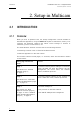
EVS Multicam Version 10.01 – Configuration Manual Issue 10.01.I EVS Broadcast Equipment SA – October 2009 1. Introduction 1.1 PURPOSE AND STRUCTURE The aim of this manual is to describe the various configuration parameters that have to be defined when you work on a server either in Multicam LSM mode or in Spotbox mode, via IPDirector or a third-party controller.
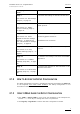
Issue 10.01.I EVS Multicam Version 10.01 – Configuration Manual EVS Broadcast Equipment SA – October 2009 2. Setup in Multicam 2.1 INTRODUCTION 2.1.1 OVERVIEW When you work in Spotbox mode, the ‘Setup Configuration’ module available in the Multicam application, using the SHIFT-F2 keyboard combination, allows you to configure the Multicam software and define server settings in relation to timecodes, protocol communication, etc.
EVS Multicam Version 10.01 – Configuration Manual Issue 10.01.I EVS Broadcast Equipment SA – October 2009 Setup page and section name Content Page 4 It includes the settings on the GPIs IN and OUT See section 2.6 ‘GPI Settings (Page 4), on page 20 Page 5 See section 2.7 ‘RS422 Protocol Settings (Page 5)’, on page 25 Page 6 It includes detailed settings on: See section 2.8 ‘HCTX Gigabit Connection Settings (Page 6)’, on page 28 and 2.
Issue 10.01.I EVS Multicam Version 10.01 – Configuration Manual EVS Broadcast Equipment SA – October 2009 2.2 GENERAL SETTINGS (PAGE 1) 2.2.1 INTRODUCTION The first page of the Setup Configuration module contains some parameters from the Setup menu of the LSM Remote Panel that are useful to adjust when working in a Spotbox mode.
EVS Multicam Version 10.01 – Configuration Manual Issue 10.01.I EVS Broadcast Equipment SA – October 2009 2.2.3 OSD SETTINGS You can also define the OSD settings on page 1.1 or 5.1 of the setup menu on the Remote Panel. You will find a description of these settings in the Multicam user manual. G ENLOCK E RROR M SG Possible values: Yes (default) / No This function enables or disables the Genlock information on the output monitor.
Issue 10.01.I EVS Multicam Version 10.01 – Configuration Manual EVS Broadcast Equipment SA – October 2009 A UDIO M ETERS ON OSD Possible values: Yes (default) / No This parameter enables/disables the display of audio meters at the bottom of each output monitor. A UDIO M ETERS A DJ .( D B) Possible range: -12 to +12 by 2 dB steps. Default: 0 dB This parameter allows adjusting the sensitivity of audio meters on the OSD of the output monitors. A positive value means that the meters will be more sensitive.
EVS Multicam Version 10.01 – Configuration Manual Issue 10.01.I EVS Broadcast Equipment SA – October 2009 The values from the following fields can be used to automatically name clips: Value Meaning Disabled No name is assigned to a clip when it is created. Default value. TC IN The time code of the IN point of the clip is automatically assigned to a clip when it is created. CAM Name The name of the recorder channel is automatically assigned to a clip when it is created.
Issue 10.01.I EVS Multicam Version 10.01 – Configuration Manual EVS Broadcast Equipment SA – October 2009 D ELETING A K EYWORD F ILE F ROM THE S ETUP S CREEN Move the cursor to the Keywords File parameter using the / SHIFT- keys, then press CTRL-DEL, and confirm whether you want to delete the current keywords file from disk, or not. D ATE F ORMAT (dd/mm/yy) This is the date format used for the dates in searches or in clip information display.
EVS Multicam Version 10.01 – Configuration Manual Issue 10.01.I EVS Broadcast Equipment SA – October 2009 2.2.7 VGA SETTINGS You can also define the VGA and RMT Sync setting on page 6.2 of the setup menu on the Remote Panel. You will find a description of these settings in the Multicam user manual. 2.2.8 VGA & RMT SYNC Possible values: No, Yes, Server Nbr This parameter selects whether and how the current clips machine, page and bank of VGA screens and EVS Remote Panel must be synchronized. 2.2.
Issue 10.01.I EVS Multicam Version 10.01 – Configuration Manual EVS Broadcast Equipment SA – October 2009 2.2.10 RS422 PROTOCOLS ID T YPE This parameter specifies the clip ID used by the protocols to access and to identify the clips. Possible values: ID LSM (default) / UmID At any time, the VDCP protocol can decide to use either the default value or the VarID. This VarID has to be set up in the section 2.7 ‘RS422 Protocol Settings (Page 5)’, on page 25. 2.2.
EVS Multicam Version 10.01 – Configuration Manual Issue 10.01.I EVS Broadcast Equipment SA – October 2009 For more information on the settings related to the timecode jump tables, refer to the sections below. For more information on the settings related to the definition and monitoring of timecode jumps, refer to section on the timecode statuses in the Server Monitoring section of the XT Tech Ref Software manual.
Issue 10.01.I EVS Multicam Version 10.01 – Configuration Manual EVS Broadcast Equipment SA – October 2009 Possible Values The values can be the following: • LTC LTC timecode, which is automatically stored in the LTC table. It is specified in the LTC field • USER User-defined timecode, which is stored in the USER TC table and specified in the USER field.
EVS Multicam Version 10.01 – Configuration Manual Issue 10.01.I EVS Broadcast Equipment SA – October 2009 2.3 VITC/ANC TIMECODE MANAGEMENT (PAGE 2) The second page available in the Setup Configuration menu ( SHIFT-F2) on servers allows the channel-by-channel management of VITC or ANC TC management. It also allows the users to clean or not the VBI information: the VITC being recorded in the active video lines, it can be disrupted in play var because of interpolation or parity violation on some fields.
Issue 10.01.I EVS Multicam Version 10.01 – Configuration Manual EVS Broadcast Equipment SA – October 2009 The following parameters can be defined: IN LOOP D-VITC The TC and user bits are always written on the SD outputs of the record codec and are the same as on the source video. Lines Lines on which the VITC must be written on the output connectors of the record codec. By default, these are lines 14-16 in NTSC and 19-21 in PAL.
EVS Multicam Version 10.01 – Configuration Manual Issue 10.01.I EVS Broadcast Equipment SA – October 2009 2.3.2 VITC/ANC MANAGEMENT IN HD IN AND HD/SD OUT In HD, the page is as follows: The following parameters can be defined: IN LOOP D-VITC The TC and user bits are always written on the monitoring SD outputs of the record codec and are the same as on the source video. Lines Lines on which the VITC must be written on the monitoring output connectors of the record codec.
Issue 10.01.I EVS Multicam Version 10.01 – Configuration Manual EVS Broadcast Equipment SA – October 2009 UserBits Yes/No flag to specify if the user bits have to be inserted in the output. The default value is ‘Yes’. HANC VITC Field to specify if embedded timecode has to be inserted in the output. The value specified has to be the same as for the HANC LTC field. The possible values are: No No new timecode inserted in the output. In (default) Same timecode as in the input inserted in the output.
EVS Multicam Version 10.01 – Configuration Manual Issue 10.01.I EVS Broadcast Equipment SA – October 2009 2.4 SDTI NETWORK PRIORITIES (PAGE 3) On the third page of the Setup Configuration module ( SHIFT-F2), it is possible to define a higher priority for a player channel of the local server whenever they play network clips/trains. This higher priority will only apply in play, not in shuttle mode.
Issue 10.01.I EVS Multicam Version 10.01 – Configuration Manual EVS Broadcast Equipment SA – October 2009 A CTIVATE / D EACTIVATE VANC D ATA PACKET SUPPORT In the Setup Configuration module ( SHIFT-F2), press the PgDn key until you access the SMPTE 334M Packet Management section. You can turn on/off the SMPTE 334M packet decoding for each record channel. You can turn on/off the SMPTE 334M packet encoding for each player channel.
EVS Multicam Version 10.01 – Configuration Manual Issue 10.01.I EVS Broadcast Equipment SA – October 2009 The limitations are: The data are re-encoded in the same order as they were in HD, but not necessarily on the same lines. If VITC in inserted in the downconverted output, no SMPTE 334M data will be inserted on the lines carrying the VITC. K EEPING C USTOM U NCOMPRESSED D ATA Upon request, it is possible to customise the decoding of the SMPTE 334M data.
Issue 10.01.I EVS Multicam Version 10.01 – Configuration Manual EVS Broadcast Equipment SA – October 2009 2.6 GPI SETTINGS (PAGE 4) On the fourth page of the Setup Configuration module ( SHIFT-F2), it is possible to define GPI settings: 2.6.1 GPI TYPES Three types of GPIs are available to be used on the servers: • Relay GPIs, which are always GPIs OUT, numbered from 1 to 4. • OPTO GPIs, which are always GPIs IN, numbered from 1 to 4.
EVS Multicam Version 10.01 – Configuration Manual Issue 10.01.I EVS Broadcast Equipment SA – October 2009 2.6.2 GPI-RELATED INFORMATION The following information is defined for each individual GPI IN: Setting Description # GPI number Channel/Device Server channel or external device that will send the GPI. Port Port on which the server will receive the GPI. Function Operation executed by the server when receiving the given GPI IN.
Issue 10.01.I EVS Multicam Version 10.01 – Configuration Manual EVS Broadcast Equipment SA – October 2009 Setting GPI Delay Description Exit ASP Initiates a command to exit the loop as soon as possible without playing the current element until its end and jump to the selected element. This GPI is used with playlists in IPDirector. Exit OUT Initiates a command to exit the loop as soon as the OUT point of the current element is reached and jump to the selected element.
EVS Multicam Version 10.01 – Configuration Manual Issue 10.01.I EVS Broadcast Equipment SA – October 2009 2.6.3 HOW TO MODIFY THE TYPE OF TTL GPIS To modify the type of TTL GPIs, proceed as follows: 1. Press the key to select the field on the first line of Page 4. 2. Press the ←and → arrows to change the value. Depending on the type defined, the lines 5 to 8 will automatically move from one GPI section to the other.
Issue 10.01.I EVS Multicam Version 10.01 – Configuration Manual EVS Broadcast Equipment SA – October 2009 2.6.5 USE OF GPIS WITH PROTOCOLS L IMITATIONS FOR P ROTOCOLS • For all protocols (excepted AVSP), use the channel assignment (PGM1-6), not the device protocol type (Sony BVW75, Odetics). • AVSP does not require any GPI IN setting in the Setup menu because they are defined through specific serial AVSP commands.
EVS Multicam Version 10.01 – Configuration Manual Issue 10.01.I EVS Broadcast Equipment SA – October 2009 2.7 RS422 PROTOCOL SETTINGS (PAGE 5) In the Setup Configuration module (SHIFT-F2), press the Page Down key until you access the page 5. It displays the VarID settings for the VDCP protocol. These settings make it possible for the VDCP protocol to use the VarID to access the clip IDs on a server or XNet network. Important: The settings in this page are only applicable to the VDCP protocol. 2.7.
Issue 10.01.I EVS Multicam Version 10.01 – Configuration Manual EVS Broadcast Equipment SA – October 2009 2.7.3 CONFLICT WITH XNET DEFINED VALUES If any of the VarID settings does not correspond to the network defined values set on the XNet, the server will be disconnected from the network and work in local mode. In this case, the following happens: • The setup screen clearly displays the message “ !Not XNet common value!” in yellow next to the incorrect parameter.
EVS Multicam Version 10.01 – Configuration Manual Issue 10.01.I EVS Broadcast Equipment SA – October 2009 The settings are described in the table below: Setting Description VarID The VarID parameters will be set up differently depending on the protocol used. Uniqueness This setting specifies whether the VarID will be unique at the XNet network level (Global) of at the XT level (Local). The default value is ‘Local’.
Issue 10.01.I EVS Multicam Version 10.01 – Configuration Manual EVS Broadcast Equipment SA – October 2009 2.8 HCTX GIGABIT CONNECTION SETTINGS (PAGE 6) 2.8.1 INTRODUCTION In the Setup Configuration module ( SHIFT-F2), press the Page Down key until you access the page 6. It displays the connection parameters for the HCTX board and the MTPC board. From Multicam 9, the servers support a Gigabit Ethernet connection. It allows the backup of the audio and video data without going through the SDTI network.
EVS Multicam Version 10.01 – Configuration Manual Issue 10.01.I EVS Broadcast Equipment SA – October 2009 2.8.2 SETTINGS DESCRIPTION The HCTX Gigabit connection settings are described in the table below: Port #1 / Port #2 IP Address Specifies the IP address to connect to port 1 / port 2 of the Gigabit Ethernet connection on the server. The IP addresses 0.0.0.0 and 255.255.255.255 are not allowed.
Issue 10.01.I EVS Multicam Version 10.01 – Configuration Manual EVS Broadcast Equipment SA – October 2009 The XNetMonitor will use the LAN IP connection to transfer the moniroting data. 2.9.2 SETTINGS DESCRIPTION The MTPC board connection settings are described in the table below: Port #1 IP Address Specifies the IP address to connect to the port 1 of the MTPC board on the server. The IP addresses 0.0.0.0 and 255.255.255.255 are not allowed.
EVS Multicam Version 10.01 – Configuration Manual Issue 10.01.I EVS Broadcast Equipment SA – October 2009 2.10 SONY BVW75 SETTINGS (PAGE 7) Page 7 of the Setup Configuration module allows the administrator to specify the settings that will be used with the Sony BVW75 protocol.
Issue 10.01.I EVS Multicam Version 10.01 – Configuration Manual EVS Broadcast Equipment SA – October 2009 Setting Name Description be accessed with the protocol. Audio Slow Motion Specifies whether or not the audio is muted in slow motion. 2.11 EDITREC SETTINGS (PAGE 8/9) Page 8 and 9 of the Setup Configuration module allows the administrator to specify the settings that will be used by the EditRec feature. 2.11.
EVS Multicam Version 10.01 – Configuration Manual Issue 10.01.I EVS Broadcast Equipment SA – October 2009 channels on a blue background: PROTOCOL: EditRec 1 Setting Port#1 When an EditRec engine is not set up on on the server, the first line on the EditRec settings page will display the following message: PROTOCOL: EditRec 2 Setting !Not Detected! 2.11.3 SETTINGS This section describes the settings that need to or can be defined with the EditRec protocol.
Issue 10.01.I EVS Multicam Version 10.01 – Configuration Manual EVS Broadcast Equipment SA – October 2009 Setting Name Description Insert TC to SDI Timecode inserted in the VITC in SD or in the HANC in HD when the playlist is played out on the EditRec player channel. Possible values: • Edit TC: playlist timecode based on the Start TC defined. • LTC: clip timecode from the LTC table. • User TC: clip timecode from the USER TC table.
EVS Multicam Version 10.01 – Configuration Manual Issue 10.01.I EVS Broadcast Equipment SA – October 2009 P LAYLIST S ETTINGS Setting Name Description Load PL Allows the user to load the playlist having the specified LSM ID. Press ENTER to execute. Rename PL Allows the user to rename the loaded playlist (max. 12 characters). Press ENTER to execute. Default PL Playlist loaded by default when the EditRec is started. Clear PL Allows the user to clear the specified playlist.
Issue 10.01.I EVS Multicam Version 10.01 – Configuration Manual EVS Broadcast Equipment SA – October 2009 A UDIO S ETTINGS Setting Name Description Edit Audio Fade Audio effect to be applied to the clip boundaries and included in the clip material. Edit Undo Cancels the last EditRec action. You can undo the last 9 actions. 2.12 MULTIVIEWER SETTINGS (PAGE 10) The Page 10 of the Setup Configuration module makes it possible to specify the settings for a multiviewer connected to the server. 2.12.
EVS Multicam Version 10.01 – Configuration Manual Issue 10.01.I EVS Broadcast Equipment SA – October 2009 2.12.2 SETTINGS As usual in the SHIFT-F2 screens, you move from one field to the over with the key and you change the value of a field by means of the arrow keys. D ISPLAY S ETTINGS Multiviewer Composition The number of recorder or player channels to be displayed and the multiviewer composition are defined in the field below: The selected composition is shown on the schema on the right.
Issue 10.01.I EVS Multicam Version 10.01 – Configuration Manual EVS Broadcast Equipment SA – October 2009 Displayed Channels For each source, you need to specify which recorder channel (CAM A to CAM F max.) or player channel (PGM1 to PGM6 max.) available in the current channel configuration should be displayed. If you select ‘None’, no image is displayed.
EVS Multicam Version 10.01 – Configuration Manual Issue 10.01.I EVS Broadcast Equipment SA – October 2009 2.13 SAVING AND LOADING SETUP FILES Twenty setup files can be saved on the XT system disk. 2.13.1 HOW TO SAVE CURRENT SETUP To save the current setup, proceed as follows: 1. Press F4. 2. Enter a file name. The file name contains max. 8 characters, no space or special character. 3. Press ENTER. 2.13.2 HOW TO LOAD A SETUP FILE 1. Press F5. 2. Select the desired file with the ↑ /↓ arrow keys.
Issue 10.01.I EVS Multicam Version 10.01 – Configuration Manual EVS Broadcast Equipment SA – October 2009 3. Setup from the Remote Panel 3.1 INTRODUCTION When you work in LSM mode, the Setup menu available on the Remote Panel allows you to define parameters. The values assigned to the parameters are saved as soon as they are assigned. Important Prior to using Multicam, the operator should enter the Setup menu and set all necessary parameters.
EVS Multicam Version 10.01 – Configuration Manual Issue 10.01.I EVS Broadcast Equipment SA – October 2009 Note The operational buttons have PRIMARY and SECONDARY functions and are divided into upper and lower sections. By pressing the SHIFT button you gain access to the secondary functions.
Issue 10.01.I EVS Multicam Version 10.01 – Configuration Manual EVS Broadcast Equipment SA – October 2009 3.3 HOW TO ACCESS THE SETUP MENU To access the Setup menu, proceed as follows: 1. If you are in Playlist mode, press RECORD first to exit this mode. 2. Press SHIFT + MENU key to go to the Main menu: 3. Split Paint 1PGM+PRV 2/3 PGM Target Setup Select Setup by pressing SHIFT + D to enter the Setup menu.
EVS Multicam Version 10.01 – Configuration Manual Issue 10.01.I EVS Broadcast Equipment SA – October 2009 • To leave a section and go back to the main page of the Setup menu (see screenshot below), press the MENU key. • To exit the Setup menu when you are in the main page of the Setup menu, press the MENU key. 3.5 HOW TO SELECT AND TO MODIFY PARAMETERS To modify the parameters, you can proceed as follows for most of the parameters: 3.6 1. Go to the desired page as explained in the Section 3.4. 2.
Issue 10.01.I EVS Multicam Version 10.01 – Configuration Manual EVS Broadcast Equipment SA – October 2009 3.7 OSD SETTINGS OSD Settings [F1]Genlock Error Msg: [F2]Disk Error Msg : [F3]Network Error Msg: [F4]Cue number on OSD: [F5]Keyword info : p.1.1 Yes Yes Yes Yes No [Menu]Quit [Clr+F_]Dft [F9]PgUp [F0]PgDn 3.7.1 GENLOCK ERROR MSG Possible values: Yes (default) / No This function enables or disables the Genlock information on the output monitor.
EVS Multicam Version 10.01 – Configuration Manual Issue 10.01.I EVS Broadcast Equipment SA – October 2009 3.7.4 CUE NUMBER ON OSD Possible values: Yes (default) / No When set to “ Yes” , the cue number is displayed on the OSD of the output monitors when a cue point is recalled inside a record train. 3.7.5 KEYWORD INFO Possible values: No (default) / Yes Up to 3 keywords and a ranking can be assigned to every clip.
Issue 10.01.I EVS Multicam Version 10.01 – Configuration Manual EVS Broadcast Equipment SA – October 2009 3.8.3 AUTO MAKE CLIP FOR CAM C Possible values: Yes (default) / No Make clip on CAM C even if no IN or OUT point has been marked on this one. 3.8.4 AUTO MAKE CLIP FOR CAM D Possible values: Yes (default) / No Make clip on CAM D even if no IN or OUT point has been marked on this one. 3.8.
EVS Multicam Version 10.01 – Configuration Manual Issue 10.01.I EVS Broadcast Equipment SA – October 2009 Record Trains p.2.2 [F1]Guardbands : 05s00fr [F2]Default clip duration : 04s00fr [F3]Mark cue points : Live [F4]Preroll : 02s00fr [F5]Record trains OUTs : Play Through [F6]Freeze on cue points : No [Menu]Quit [Clr+F_]Dft [F9]PgUp [F0]PgDn 3.8.7 GUARDBANDS Range: from 00s00fr to 60s00fr. Default: 05s00fr This option specifies the amount of «guardband» before and after clips. 3.8.
Issue 10.01.I EVS Multicam Version 10.01 – Configuration Manual EVS Broadcast Equipment SA – October 2009 3.8.11 RECORD TRAIN OUTS Possible values: Play through (default) / Freeze When this parameter is set to “ Freeze” , and an train, Multicam will countdown to the OUT point picture (if the Post-Roll mode is disabled) or duration (if the Post-Roll mode is enabled) when OUT point is marked in a record and automatically freeze on that on that picture + the Post-Roll replaying that section.
EVS Multicam Version 10.01 – Configuration Manual Issue 10.01.I EVS Broadcast Equipment SA – October 2009 Record Trains p.2.3 [F1]Internal Loop Mode : Video+Audio [F2]Make Clip rem. Trains : Ctrled Cams [Menu]Quit [Clr+F_]Dft [F9]PgUp [F0]PgDn 3.8.13 INTERNAL LOOP MODE Possible values: Video + Audio (default) / Video only This parameter defines which components of PGM1 output must be recorded back into the server when the Loop mode is engaged.
Issue 10.01.I EVS Multicam Version 10.01 – Configuration Manual EVS Broadcast Equipment SA – October 2009 3.9 CLIPS SETTINGS Clips [F1]Protect pages [F2]Confirm delete clips [F3]Auto name clips [F4]Clip Post-Roll [F5]Call channel VGA [F6]Clip edit by network [Menu]Quit [Clr+F_]Dft 3.9.1 p.3.
EVS Multicam Version 10.01 – Configuration Manual Issue 10.01.I EVS Broadcast Equipment SA – October 2009 3.9.2 CONFIRM DELETE CLIP Possible values: No (default) / Yes No: clips are deleted immediately Yes: a confirmation is required when deleting clips, either from the Remote or from the keyboard. Note This parameter does not apply to the Clear All Clips command (Main menu) which already has its own confirmation message. 3.9.
Issue 10.01.I EVS Multicam Version 10.01 – Configuration Manual EVS Broadcast Equipment SA – October 2009 3.9.5 CALL CHANNEL VGA Possible values: Disable (default) / Enable This parameter disables or enables the Call Channel function on the VGA Clip screen. This function allows the operator to select on which PGM channel the clips called from the keyboard/tablet and VGA should be loaded. 3.9.
EVS Multicam Version 10.01 – Configuration Manual Issue 10.01.I EVS Broadcast Equipment SA – October 2009 3.9.8 KEYWORD MODE Possible values: List (default), Numeric This parameter specifies the keyword assignment/search mode on the EVS Remote Panel: • List: It will display the keywords by groups of 8 on the LCD of the Remote Panel and the operator can select them with the corresponding F_ key.
Issue 10.01.I EVS Multicam Version 10.01 – Configuration Manual EVS Broadcast Equipment SA – October 2009 1. In the 2 n d page of Clip parameters, press the F5 key to edit the PUSH Receive Page parameter. 2. Press the F_ key corresponding to the page number you want to select/unselect as PUSH Receive Page. The selected pages will be highlighted on the LCD and the corresponding F_ keys light red. F_ keys of unselected pages light green. 3. Press ENTER to validate your selection. Clips p.3.
EVS Multicam Version 10.01 – Configuration Manual Issue 10.01.I EVS Broadcast Equipment SA – October 2009 3.9.15 GRAB IMAGE Possible values: Disable (default) / Enable When the function is enabled and a default XFile has been assigned, the grab function is coupled with the Mark key on the Remote. Each time the Mark key is used, a cue point is marked and a command is sent to the XFile to save that image. The grab can also be activated on the keyboard with the combination CTRL + G. 3.9.
Issue 10.01.I EVS Multicam Version 10.01 – Configuration Manual EVS Broadcast Equipment SA – October 2009 3.10 TIMELINE SETTINGS Timeline [F1]TL Receive Pg [F2]Mono per Track p.3.4 : 1 2 3 4 5 6 7 8 9 0 : 1 [Menu]Quit [Clr+F_]Dft [F9]PgUp [F0]PgDn 3.10.1 TL RECEIVE PAGE Default: 0 This parameter allows specifying where clips created as part of the timeline editing process will be stored. 3.10.
EVS Multicam Version 10.01 – Configuration Manual Issue 10.01.I EVS Broadcast Equipment SA – October 2009 3.11 PLAYLIST SETTINGS Playlist p.4.1 [F1]Video effect duration : 00s10fr [F2]Audio effect duration : Lock to Vid. [F3]Wipe type : Vert. L>R [F4]Default plst speed : Unk. [F5]Insert in playlist : After [F6]Confirm Ins/Del clips : No [Menu]Quit [Clr+F_]Dft [F9]PgUp [F0]PgDn 3.11.1 VIDEO EFFECT DURATION Possible range: 0s00fr to 20s00fr.
Issue 10.01.I EVS Multicam Version 10.01 – Configuration Manual EVS Broadcast Equipment SA – October 2009 3.11.4 DEFAULT PLST SPEED Possible values: Unknown (default), then from 0% to 100% This defines the default speed used for clips entered into playlist. Unknown means that the speed of the previous clip in the playlist will be used as a reference for the current clip. 0% will force the playlist to pause at the end of the previous clip. 3.11.
EVS Multicam Version 10.01 – Configuration Manual Issue 10.01.I EVS Broadcast Equipment SA – October 2009 3.11.8 EXTEND SPLIT TRANSITION Possible values: Center (on) Cut / End (on) Cut / Start (on) Cut / Ask This parameter determines how the transition should be extended when the transition duration on the audio or video track only is modified. This parameter is only useful when performing split audio editing.
Issue 10.01.I EVS Multicam Version 10.01 – Configuration Manual EVS Broadcast Equipment SA – October 2009 • Conditional: This loads t he selected playlist on the selected PGM only if only 1 channel is active when entering the PLST EDIT mode. Allows loading and playing multiple playlists using a single Remote Panel. 3.11.
EVS Multicam Version 10.01 – Configuration Manual Issue 10.01.I EVS Broadcast Equipment SA – October 2009 Note This adjustment is done during the record process. A new Lipsync value will apply for the next recorded pictures only. 3.12.3 AUDIO METERS ON OSD Possible values: Yes (default) / No This parameter enables/disables the display of audio meters at the bottom of each output monitor. 3.12.4 AUDIO METERS ADJ.(DB) Possible range: -12 to +12 by 2 dB steps.
Issue 10.01.I EVS Multicam Version 10.01 – Configuration Manual EVS Broadcast Equipment SA – October 2009 Audio p.5.2 [Menu]Quit [Clr+F_]Dft [F9]PgUp [F0]PgDn This page is intentionally left blank and is reserved for future developments. 3.13 EVS CONTROLLER SETTINGS EVS Controller p.6.
EVS Multicam Version 10.01 – Configuration Manual Issue 10.01.I EVS Broadcast Equipment SA – October 2009 OR • the speed range defined by the lever is limited to the value specified by this parameter (VarMax mode ON). 3.13.4 LEVER ENGAGE MODE Possible values: Direct (default) / Current speed The speed variation depends on the position of the T-Bar lever. • Direct mode: the lever will engage directly when moved, resulting in a speed jump to the desired speed determined by the lever arm position.
Issue 10.01.I EVS Multicam Version 10.01 – Configuration Manual EVS Broadcast Equipment SA – October 2009 3.13.6 RECALL CLIP TOGGLE Possible values: Enable (default) / Disable This option allows the operator to select the camera of a clip through the Function keys. Pressing several times the F_ key browses to CAM A, CAM B, CAM C, CAM D, CAM E and CAM F. EVS Controller [F1]Record key [F2]Pointing device [F3]VGA & RMT Sync p.6.
EVS Multicam Version 10.01 – Configuration Manual Issue 10.01.I EVS Broadcast Equipment SA – October 2009 3.13.9 VGA & RMT SYNC Possible values: No, Yes, Server Nbr This parameter selects whether and how the current clips machine, page and bank of VGA screens and EVS Remote Panel must be synchronized. Value Meaning No (Default) Clip machine, page and bank can be selected independently on the VGA screen and on the EVS Remote Panel.
Issue 10.01.I EVS Multicam Version 10.01 – Configuration Manual EVS Broadcast Equipment SA – October 2009 3.14 MAPPING NETWORK CAM Mapping network cam [F1]Authorize cam mapping Cam A Cam B [F3]Cam C [F4]Cam D p.6.3 : Yes : Local : Local : CamA/01 : CamB/01 [Menu]Quit [Clr+F_]Dft [F9]PgUp [F0]PgDn This is a software option. It allows users to map network cameras to unused camera position on the Remote up to the D camera.
EVS Multicam Version 10.01 – Configuration Manual Issue 10.01.I EVS Broadcast Equipment SA – October 2009 3.15 HYPERMOTION CONFIGURATION Hypermotion Configuration p.6.4 [F1]Hypermotion : Yes [F2]Recorder : CAM A [F6] RS422 : 6 [F3]Remote Controller : Hypermotion Only [Menu]Quit [Clr+F_]Dft [F9]PgUp [F0]PgDn The Hypermotion feature is a software option (license code 20) that allows controlling a hypermotion camera from the Remote Panel. 3.15.
Issue 10.01.I EVS Multicam Version 10.01 – Configuration Manual EVS Broadcast Equipment SA – October 2009 3.15.4 REMOTE MODE Possible values: Hypermotion only, Hypermotion + LSM The parameter specifies what the server will control: • Hypermotion only: The server controls only the hypermotion camera. When this value is selected, an additional Remote is made available in the main menu of the Remote Panel, since the hypermotion camera is considered as an additional external camera.
EVS Multicam Version 10.01 – Configuration Manual Issue 10.01.I EVS Broadcast Equipment SA – October 2009 3.16.2 RS422 #2 Possible values: EVS Remote, Sony BVW75, XtenDD35, Odetics, VDCP, EVS AVSP, EVS IPDP, Edit Rec, --------Default: EVS Remote 3.16.3 RS422 #3 Possible values: EVS Remote, Sony BVW75, XtenDD35, Odetics, VDCP, EVS AVSP, EVS IPDP, Edit Rec, --------Default: EVS Remote 3.16.
Issue 10.01.I EVS Multicam Version 10.01 – Configuration Manual EVS Broadcast Equipment SA – October 2009 3.16.7 ID TYPE Possible values: ID LSM (default) / UmID Defines the type of clip ID used by RS422 protocols (XtenDD35, Odetics, Louth VDCP, EVS AVSP) to identify clips: • ID LSM: It identifies clips using their page, bank, clip and camera number (ex: 245C).
EVS Multicam Version 10.01 – Configuration Manual Issue 10.01.I EVS Broadcast Equipment SA – October 2009 • EVS AVSP and IPDP protocols can be assigned to several channels simultaneously. If you need to assign some channels to an AirBox, you must set the main controller for these channels to EVS AVSP. If you need to assign some channels to an IP Director, you must set the main controller for these channels to EVS IPDP. 3.17.
Issue 10.01.I EVS Multicam Version 10.01 – Configuration Manual EVS Broadcast Equipment SA – October 2009 3.17.4 CONTROL TYPE Special Control Settings p.7.4 Control type OSD Display PGM1:[F1]Parallel [F5] Main PGM2:[F2]Exclusive PGM3:[F3]Exclusive PGM4:[F4]Exclusive [Menu]Quit [Clr+F_]Dft [F9]PgUp [F0]PgDn Possible Values: Parallel, Exclusive (default) This setting allows channels to either be controlled in ‘Exclusive’ control (same as allowed in the past with 2 n d Control Mode) or in Parallel Mode.
EVS Multicam Version 10.01 – Configuration Manual Issue 10.01.I EVS Broadcast Equipment SA – October 2009 3.18 IPDP REDUNDANT SERIAL LINK As explained in the XT Tech Ref Hardware manual, additional RS422 links between IPDirector workstations and the servers can be cabled to provide a failover mechanism for the IPDP protocol. 3.18.1 LSM MODE In Multicam LSM mode, you need to assign at least two RS422 ports to the IPDP protocol.
Issue 10.01.I EVS Multicam Version 10.01 – Configuration Manual EVS Broadcast Equipment SA – October 2009 3.19 GPI IN SETTINGS 3.19.1 TTL GPIS ASSIGNMENT The 4 Relay GPIs (GPIs OUT) and the 4 OPTO GPIs (GPIs IN) provide GPIs having a predefined and fixed type. The 4 TTL GPIs are switchable to GPIs IN or GPIs OUT. Depending on whether they are defined as GPIs IN or OUT, the pages related to the GPIs settings will differ. The type for the TTL GPIs, that is to say GPI IN or GPI OUT, is set on page 8.1.
EVS Multicam Version 10.01 – Configuration Manual Issue 10.01.I EVS Broadcast Equipment SA – October 2009 GPI In Settings GPI# Channel/Device 5 [F1]RMT1 -6 [F2]RMT1 -7 [F3]RMT1 -8 [F4]RMT1 -- p.8.
Issue 10.01.I EVS Multicam Version 10.01 – Configuration Manual EVS Broadcast Equipment SA – October 2009 3.19.3 GPIS IN DELAY GPI In Settings GPI# Delay 1 [F1]Disable 2 [F2]Disable 3 [F3]Disable 4 [F4]Disable GPI# 5 [F5] 6 [F6] 7 [F7] 8 [F8] p.8.
EVS Multicam Version 10.01 – Configuration Manual Issue 10.01.I EVS Broadcast Equipment SA – October 2009 Example Users can select all types of GPIs. The behaviour varies accordingly: High Low High Pulse Low Pulse Before the IN Low High Low On Replace IN High Low High Pulse Between IN and OUT High Low Low On Replace OUT Low High High Pulse After the OUT Low High Low High Low Pulse High Low Pulse High 3.19.
Issue 10.01.I EVS Multicam Version 10.01 – Configuration Manual EVS Broadcast Equipment SA – October 2009 3.20 SPECIAL EFFECTS Special Effect p.9.1 [F1]Paint/Target trans. : 00s05fr [F2]Set colour for : Cursor [F3]Colour: White [F4]Y : 240 [F5]U: 128 [F6]V: 128 [F7]Split Screen Tracking: No [Menu]Quit [Clr+F_]Dft [F9]PgUp 3.20.1 PAINT/TARGET TRANSITION Possible values: 0s01fr to 5s00fr.
EVS Multicam Version 10.01 – Configuration Manual Issue 10.01.I EVS Broadcast Equipment SA – October 2009 3.20.4 CUSTOM COLOUR F3, F4, and F5 are used to set the border colour for the split screen, the wipe effect and the cursor Custom Y: (0 – 360) Default: 240 Custom U: (0 – 128) Default: 128 Custom V: (0 – 128) Default: 128 3.20.5 SPLITSCREEN TRACKING Possible values: No (default) / Yes This setting enables or disables the auto-tracking inside the Split Screen effect. Special Effect p.9.
Issue 10.01.I EVS Multicam Version 10.01 – Configuration Manual EVS Broadcast Equipment SA – October 2009 4. XNet SDTI Network 4.1 OVERVIEW The XNet network is composed by several servers all connected with a 75-Ohm coaxial cable (BNC). The exchange between systems is operated through the SDTI interface at 540 or 1485 Mbps. The XNet network requires a network server dedicated to the management of the database shared among all servers.
EVS Multicam Version 10.01 – Configuration Manual Issue 10.01.I EVS Broadcast Equipment SA – October 2009 Only servers with HCTX board with SDTI module and SDTI code can be connected to the XNet network. The XNet compatibility between versions is detailed in the release notes. 4.2 CONFIGURATION The configuration of the different servers connected to the XNet network is done via the EVS Menu, more precisely in the Network area accessible via the Maintenance menu, Configuration command. 4.
Issue 10.01.I EVS Multicam Version 10.01 – Configuration Manual EVS Broadcast Equipment SA – October 2009 unavailable. In this case the message Source LSM disconnected appears on the output monitors and the system automatically switches to the LOCAL mode for clips or/and record trains. If clips are inserted in a playlist, those clips will be temporarily considered as unavailable and will be skipped during playback.
EVS Multicam Version 10.01 – Configuration Manual Issue 10.01.I EVS Broadcast Equipment SA – October 2009 Glossary Dolby Digital Also called Dolby 5.1 or AC-3. It is an audio coding system containing up to 6 discrete channels of sound, with 5 channels for normal-range speakers (20 Hz 20,000 Hz) (Right front, Center, Left Front, Right Rear and Left Rear) and one channel (20 Hz - 120 Hz) for the LFE, or subwoofer.
Issue 10.01.I EVS Multicam Version 10.01 – Configuration Manual EVS Broadcast Equipment SA – October 2009 Regional Contacts AMERICA (NORTH & LATIN) EVS Americas Tel: +1 973 575 7811 Fax: +1 973 575 7812 Tech. line: +1 973 575 7813 usa@evs.tv EVS Canada Tel: +1 514 750 7544 Fax: +1 514 750 7518 Tech. line: +1 973 575 7813 usa@evs.tv EVS Australia Tel: +61 02 9452 8600 Fax: +61 02 9975 1368 Mobile: +61 420 307 387 sales@evs-asia.com.hk EVS China Tel: +86 10 6808 0248 Fax: +86 10 6808 0246 Tech.
EVS Multicam Version 10.01 – Configuration Manual Issue 10.01.I EVS Broadcast Equipment SA – October 2009 EUROPE, MIDDLE EAST & AFRICA EVS Middle East Tel: +971 4 365 4222 Fax: +971 4 425 3501 Mobile: +971 50 887 8758 middle-east@evs.tv EVS UK Tel: +44 1372 387 250 Fax: +44 1372 387 269 Tech. line: +44 1372 387 266 uk@evs.
EVS Broadcast Equipment Liège Science Park 16, rue Bois St Jean B-4102 Ougrée Belgium Corporate Headquarters North & Latin America Headquarters Asia & Pacific Headquarters Other regional offices available on +32 4 361 7000 +1 973 575 7811 +852 2914 2501 www.evs.tv/contact To learn more about EVS go to www.evs.