Configuration Manual Version 10.
EVS Multicam – Version 10.03 – Configuration Manual EVS Broadcast Equipment SA – July 2010 Issue 10.03.C C OPYRIGHT EVS Broadcast Equipment – Copyright © 2002-2010. All rights reserved. D ISCLAIMER The information in this manual is furnished for inform ational use only and subject to change without notice.
Issue 10.03.C EVS Multicam – Version 10.03 – Configuration Manual EVS Broadcast Equipment SA – July 2010 Table of Contents TABLE OF CONTENTS .................................................................................................... II WHAT’S NEW? ................................................................................................................. 1 1. INTRODUCTION....................................................................................................... 2 1.1 1.2 2.
EVS Multicam – Version 10.03 – Configuration Manual EVS Broadcast Equipment SA – July 2010 Issue 10.03.C Encoding of the SMPTE 334M packets on the downconverted outputs .................................................................. 19 Keeping Custom Uncompressed Data ..................................................................................................................... 20 Compatibility information ...........................................................................................
Issue 10.03.C EVS Multicam – Version 10.03 – Configuration Manual EVS Broadcast Equipment SA – July 2010 3.7.1 Genlock Error Msg ................................................................................................................46 3.7.2 Disk Error Msg ......................................................................................................................46 3.7.3 Network Error Msg ...................................................................................................
EVS Multicam – Version 10.03 – Configuration Manual EVS Broadcast Equipment SA – July 2010 Issue 10.03.C 3.11.8 Extend Split Transition ..........................................................................................................63 3.11.9 Swap Audio Tracks ...............................................................................................................63 3.11.10 Playlist Loop.........................................................................................................
Issue 10.03.C EVS Multicam – Version 10.03 – Configuration Manual EVS Broadcast Equipment SA – July 2010 3.19.2 GPIs IN Definition .................................................................................................................79 3.19.3 GPIs IN Delay .......................................................................................................................81 3.19.4 GPIs OUT Definition.............................................................................................
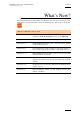
EVS Multicam – Version 10.03 – Configuration Manual Issue 10.3.C EVS Broadcast Equipment SA – July 2010 What’s New? The changes linked to new features on Multicam version 10.03 are listed in the table below, and are identified in the user manual by the ‘New’ logo in the margin Updates for Multicam version 10.03 Section 2.2.5 Default use of the GigE or SDTI network for copy operations: Default Copy/Move option in the SHIFT-F2. Sections 2.10 & 2.11 New Sony BVW75 and EditRec settings Section 3.9.
Issue 10.03.C EVS Multicam – Version 10.03 – Configuration Manual EVS Broadcast Equipment SA – July 2010 1. Introduction 1.1 PURPOSE AND STRUCTURE The aim of this manual is to describe the various configuration parameters that have to be defined when you work on a server either in Multicam LSM mode or in Spotbox mode, via IPDirector or a third-party controller.
EVS Multicam – Version 10.03 – Configuration Manual Issue 10.3.C EVS Broadcast Equipment SA – July 2010 2. Setup in Multicam 2.1 INTRODUCTION 2.1.1 OVERVIEW When you work in Spotbox mode, the ‘Setup Configuration’ module available in the Multicam application, using the SHIFT-F2 keyboard combination, allows you to configure the Multicam software and define server settings in relation to timecodes, protocol communication, etc.
Issue 10.03.C EVS Multicam – Version 10.03 – Configuration Manual EVS Broadcast Equipment SA – July 2010 Setup page and section name Content on page 26. Page 6 It includes detailed settings on: See section 2.8 ‘HCTX Gigabit Connection Settings (Page 6)’, on page 29 and 2.9 ‘LAN Connection Settings (Page 6)’, on page 30. the HCTX gigabit connection Page 7 It includes the settings used with the Sony BVW protocol. See section 2.10 ‘Sony BVW75 Settings (Page 7)’, on page 32.
EVS Multicam – Version 10.03 – Configuration Manual EVS Broadcast Equipment SA – July 2010 2.2 GENERAL SETTINGS (PAGE 1) 2.2.1 INTRODUCTION Issue 10.3.C The first page of the Setup Configuration module contains some parameters from the Setup menu of the LSM Remote Panel that are useful to adjust when working in a Spotbox mode.
Issue 10.03.C EVS Multicam – Version 10.03 – Configuration Manual EVS Broadcast Equipment SA – July 2010 G ENLOCK E RROR M SG Possible values: Yes (default) / No This function enables or disables the Genlock information on the output monitor. If Genlock reference is not correct, the !GkV message appears on the output monitor. D ISK E RROR M SG Possible values: Yes (default) / No This function displays an error message (!Raid) on the output monitor when a disk is faulty.
EVS Multicam – Version 10.03 – Configuration Manual EVS Broadcast Equipment SA – July 2010 Issue 10.3.C A UDIO M ETERS A DJ . ( D B) Possible range: -83.2dB to 0dB. Default: 0dB This parameter allows adjusting the sensitivity of audio meters on the OSD of the output monitors. A positive value means that the meters will be more sensitive. 2.2.4 NETWORK SETTINGS You can also define the Clip edit by network setting on page 3.1, F6 of the setup menu on the Remote Panel.
Issue 10.03.C EVS Multicam – Version 10.03 – Configuration Manual EVS Broadcast Equipment SA – July 2010 The values from the following fields can be used to automatically name clips: Value Meaning Disabled No nam e is assigned to a clip when it is created. Default value. TC IN The timecode of the IN point of the clip is automatically assigned to a clip when it is created. CAM Name The name of the recorder channel is automatically assigned to a clip when it is created.
EVS Multicam – Version 10.03 – Configuration Manual EVS Broadcast Equipment SA – July 2010 Issue 10.3.C D ELETING A K EYWORD F ILE F ROM THE S ETUP S CREEN Move the cursor to the Keywords File parameter using the / SHIFT- keys, then press CTRL-DEL, and confirm whether you want to delete the current keywords file from disk, or not. D ATE F ORMAT (dd/mm/yy) This is the date form at used for the dates in searches or in clip inform ation display.
Issue 10.03.C 2.2.7 EVS Multicam – Version 10.03 – Configuration Manual EVS Broadcast Equipment SA – July 2010 VGA SETTINGS You can also define the VGA and RMT Sync setting on page 6.2 of the setup menu on the Remote Panel. You will find a description of these settings in the Multicam user manual. 2.2.8 VGA & RMT SYNC Possible values: No, Yes, Server Nbr This parameter selects whether and how the current clips machine, page and bank of VGA screens and EVS Remote Panel must be synchronized. 2.2.
EVS Multicam – Version 10.03 – Configuration Manual EVS Broadcast Equipment SA – July 2010 Issue 10.3.C 2.2.10 RS422 PROTOCOLS ID T YPE This parameter specifies the clip ID used by the protocols to access and to identify the clips. Possible values: ID LSM (default) / UmID At any time, the VDCP protocol can decide to use either the default value or the VarID. This VarID has to be set up in the section 2.7 ‘RS422 Protocol Settings (Page 5)’, on page 26. 2.2.
Issue 10.03.C EVS Multicam – Version 10.03 – Configuration Manual EVS Broadcast Equipment SA – July 2010 For more information on the settings related to the timecode jump tables, refer to the sections below. For more information on the settings related to the definition and monitoring of timecode jumps, refer to section on the timecode statuses in the Server Monitoring section of the XT Tech Ref Software manual.
EVS Multicam – Version 10.03 – Configuration Manual EVS Broadcast Equipment SA – July 2010 Issue 10.3.C Possible Values The values can be the following: • LTC LTC timecode, which is automatically stored in the LTC table. It is specified in the LTC field • USER User-defined timecode, which is stored in the USER TC table and specified in the USER field.
Issue 10.03.C 2.3 EVS Multicam – Version 10.03 – Configuration Manual EVS Broadcast Equipment SA – July 2010 VITC/ANC TIMECODE MANAGEMENT (PAGE 2) The second page available in the Setup Configuration menu (SHIFT-F2) on servers allows the channel-by-channel management of VITC or ANC TC management. It also allows the users to clean or not the VBI information: the VITC being recorded in the active video lines, it can be disrupted in play var because of interpolation or parity violation on some fields.
EVS Multicam – Version 10.03 – Configuration Manual Issue 10.3.C EVS Broadcast Equipment SA – July 2010 The following parameters can be defined: IN LOOP D-VITC The TC and user bits are always written on the SD outputs of the record codec and are the same as on the source video. Lines Lines on which the VITC must be written on the output connectors of the record codec. By default, these are lines 14-16 in NTSC and 19-21 in PAL.
Issue 10.03.C 2.3.2 EVS Multicam – Version 10.03 – Configuration Manual EVS Broadcast Equipment SA – July 2010 VITC/ANC MANAGEMENT IN HD IN AND HD/SD OUT In HD, the page is as follows: The following parameters can be defined: IN LOOP D-VITC The TC and user bits are always written on the monitoring SD outputs of the record codec and are the same as on the source video. Lines Lines on which the VITC must be written on the monitoring output connectors of the record codec.
EVS Multicam – Version 10.03 – Configuration Manual Issue 10.3.C EVS Broadcast Equipment SA – July 2010 UserBits Yes/No flag to specify if the user bits have to be inserted in the output. The default value is ‘Yes’. HANC VITC Field to specify if em bedded timecode has to be inserted in th e output. The value specified has to be the same as for the HANC LTC field. The possible values are: No No new timecode inserted in the output. In (default) Same timecode as in the input inserted in the output.
Issue 10.03.C 2.4 EVS Multicam – Version 10.03 – Configuration Manual EVS Broadcast Equipment SA – July 2010 SDTI NETWORK PRIORITIES (PAGE 3) On the third page of the Setup Configuration module (SH IFT-F2), it is possible to define a higher priority for a player channel of the local server whenever they play network clips/trains. This higher priority will only apply in play, not in shuttle mode.
EVS Multicam – Version 10.03 – Configuration Manual EVS Broadcast Equipment SA – July 2010 Issue 10.3.C A CTIVATE / D EACTIVATE VANC D ATA PACKET SUPPORT In the Setup Configuration module (SHIFT-F2), press the PgDn key until you access the SM PTE 334M Packet Management section. You can turn on/off the SM PTE 334M packet decoding for each record channel. You can turn on/off the SM PTE 334M packet encoding for each player channel.
Issue 10.03.C EVS Multicam – Version 10.03 – Configuration Manual EVS Broadcast Equipment SA – July 2010 The limitations are: The data are re-encoded in the same order as they were in HD, but not necessarily on the same lines. If VITC in inserted in the downconverted output, no SMPTE 334M data will be inserted on the lines carrying the VITC. K EEPING C USTOM U NCOMPRESSED D ATA Upon request, it is possible to custom ize the decoding of the SMPTE 334M data.
EVS Multicam – Version 10.03 – Configuration Manual EVS Broadcast Equipment SA – July 2010 2.6 Issue 10.3.C GPI SETTINGS (PAGE 4) On the fourth page of the Setup Configuration module (SHIFT-F2), it is possible to define GPI settings: 2.6.1 GPI TYPES Three types of GPIs are available to be used on the servers: • Relay GPIs, which are always GPIs OUT, numbered from 1 to 4. • OPTO GPIs, which are always GPIs IN, numbered from 1 to 4.
Issue 10.03.C 2.6.2 EVS Multicam – Version 10.03 – Configuration Manual EVS Broadcast Equipment SA – July 2010 GPI-RELATED INFORMATION The following information is defined for each individual GPI IN: Setting Description # GPI number Channel/Device Server channel or external device that will send the GPI. Port Port on which the server will receive the GPI. Function Operation executed by the server when receiving the given GPI IN.
EVS Multicam – Version 10.03 – Configuration Manual Issue 10.3.C EVS Broadcast Equipment SA – July 2010 Setting GPI Delay Description Exit ASP Initiates a command to exit the loop as soon as possible without playing the current element until its end and jump to the selected element. This GPI is used with playlists in IPDirector. Exit OUT Initiates a command to exit the loop as soon as the OUT point of the current element is reached and jump to the selected element.
Issue 10.03.C 2.6.3 EVS Multicam – Version 10.03 – Configuration Manual EVS Broadcast Equipment SA – July 2010 HOW TO MODIFY THE TYPE OF TTL GPIS To modify the type of TTL GPIs, proceed as follows: 1. Press the key to select the field on the first line of Page 4. 2. Press the ←and → arrows to change the value. Depending on the type defined, the lines 5 to 8 will automatically move from one GPI section to the other.
EVS Multicam – Version 10.03 – Configuration Manual EVS Broadcast Equipment SA – July 2010 2.6.5 Issue 10.3.C USE OF GPIS WITH PROTOCOLS L IMITATIONS FOR P ROTOCOLS • For all protocols (excepted AVSP), use the channel assignment (PGM1-6), not the device protocol type (Sony BVW75, Odetics). • AVSP does not require any GPI IN setting in the Setup menu because they are defined through specific serial AVSP commands.
Issue 10.03.C 2.7 EVS Multicam – Version 10.03 – Configuration Manual EVS Broadcast Equipment SA – July 2010 RS422 PROTOCOL SETTINGS (PAGE 5) In the Setup Configuration module (SHIFT-F2), press the Page Down key until you access the page 5. It displays the VarID settings for the VDCP protocol. These settings make it possible for the VDCP protocol to use the VarID to access the clip ID s on a server or XN et netw ork. Important: The settings in this page are only applicable to the VDCP protocol. 2.7.
EVS Multicam – Version 10.03 – Configuration Manual EVS Broadcast Equipment SA – July 2010 2.7.3 Issue 10.3.C CONFLICT WITH XNET DEFINED VALUES If any of the VarID settings does not correspond to the network defined values set on the XNet, the server will be disconnected from the network and work in local mode. In this case, the following happens: • The setup screen clearly displays the message “ !Not XNet common value!” in yellow next to the incorrect parameter.
Issue 10.03.C EVS Multicam – Version 10.03 – Configuration Manual EVS Broadcast Equipment SA – July 2010 The settings are described in the table below: Setting Description VarID The VarID parameters will be set up differently depending on the protocol used. Uniqueness This setting specifies whether the VarID will be unique at the XNet network level (Global) of at the XT level (Local). The default value is ‘Local’.
EVS Multicam – Version 10.03 – Configuration Manual EVS Broadcast Equipment SA – July 2010 Issue 10.3.C 2.8 HCTX GIGABIT CONNECTION SETTINGS (PAGE 6) 2.8.1 INTRODUCTION In the Setup Configuration module (SHIFT-F2), press the Page Down key until you access the page 6. It displays the connection parameters for the HCTX board and the MTPC board. From Multicam 9, the servers support a Gigabit Ethernet connection. It allows the backup of the audio and video data without going through the SDTI network.
Issue 10.03.C 2.8.2 EVS Multicam – Version 10.03 – Configuration Manual EVS Broadcast Equipment SA – July 2010 SETTINGS DESCRIPTION The HCTX Gigabit connection settings are described in the table below: Port #1 / Port #2 IP Address Specifies the IP address to connect to port 1 / port 2 of the Gigabit Ethernet connection on the server. The IP addresses 0.0.0.0 and 255.255.255.255 are not allowed.
EVS Multicam – Version 10.03 – Configuration Manual EVS Broadcast Equipment SA – July 2010 2.9.2 Issue 10.3.C SETTINGS DESCRIPTION The MTPC board connection settings are described in the table below: Port #1 IP Address Specifies the IP address to connect to the port 1 of the MTPC board on the server. The IP addresses 0.0.0.0 and 255.255.255.255 are not allowed. Subnet Mask Specifies the range of logical addresses within the address space assigned to the MTPC board connection.
Issue 10.03.C 2.10 EVS Multicam – Version 10.03 – Configuration Manual EVS Broadcast Equipment SA – July 2010 SONY BVW75 SETTINGS (PAGE 7) Page 7 of the Setup Configuration module allows the administrator to specify the settings that will be used with the Sony BVW75 protocol.
EVS Multicam – Version 10.03 – Configuration Manual EVS Broadcast Equipment SA – July 2010 Issue 10.3.C Setting Name Description Audio Slow Motion Specifies whether or not the audio is muted in slow motion. SONY Parallel Status Allows activating Sony serial status reporting when several controllers are used in parallel mode.
Issue 10.03.C EVS Multicam – Version 10.03 – Configuration Manual EVS Broadcast Equipment SA – July 2010 2.11 EDITREC SETTINGS (PAGE 8/9) Page 8 and 9 of the Setup Configuration module allows the adm inistrator to specify the settings that will be used by the EditRec feature. 2.11.1 INTRODUCTION TO EDITREC EditRec is a linear editing engine that is associated to a player channel and a recorder channel of a server in order to emulate a VTR. The EditRec engine relies on the EditRec protocol.
EVS Multicam – Version 10.03 – Configuration Manual EVS Broadcast Equipment SA – July 2010 Issue 10.3.C 2.11.3 SETTINGS This section describes the settings that need to or can be defined with the EditRec protocol. C HANGING S ETTINGS You can only edit the settings when the EditRec player channel is stopped. When you leave a field followed by [ENTER], you need to select ENTER and press the ENTER key on the keyboard to apply the changes.
Issue 10.03.C EVS Multicam – Version 10.03 – Configuration Manual EVS Broadcast Equipment SA – July 2010 OSD S ETTINGS Setting Name Description Super Activates (Yes) or deactivates (No) the OSD. Display Sel. Fields to appear on the OSD.
EVS Multicam – Version 10.03 – Configuration Manual Issue 10.3.C EVS Broadcast Equipment SA – July 2010 Setting Name Description Clear PL Allows clearing the specified playlist. You can choose to delete only the EDL only or the EDL and the clips. Select the values and press ENTER to execute. CLEAR UNUSED EDITREC CLIPS Deletes all unused EditRec clips on the local server. A confirmation is requested. Close Edit Finalizes the editing and closes the loaded playlist.
Issue 10.03.C EVS Multicam – Version 10.03 – Configuration Manual EVS Broadcast Equipment SA – July 2010 2.12 MULTIVIEWER SETTINGS (PAGE 10) The Page 10 of the Setup Configuration module makes it possible to specify the settings for a multiviewer connected to the server. 2.12.1 INTRODUCTION When an optional multiviewer board is installed on the server, you can monitor the server channels on a multiviewer.
EVS Multicam – Version 10.03 – Configuration Manual EVS Broadcast Equipment SA – July 2010 Issue 10.3.C The selected composition is shown on the schema on the right. The following compositions are possible: Value Composition 4 (2+2) 2 split images at the top and 2 at the bottom. This is the default composition for XT[2] 4U. 6 (4+2) 4 small split images at the top and 2 large split images at the bottom of the screen. This is impossible to display the same source in small and large size.
Issue 10.03.C EVS Multicam – Version 10.03 – Configuration Manual EVS Broadcast Equipment SA – July 2010 A SPECT R ATIO S ETTINGS In the Videos field of the Aspect Ratio group box, you can change the aspect ratio of the video in HD. The following aspect ratios are available: • 16:9 Anamorphic (default) • Crop • 4:3 aspect In the SD downconverted field of the Aspect Ratio group box, you can change the aspect ratio of the video in SD .
EVS Multicam – Version 10.03 – Configuration Manual EVS Broadcast Equipment SA – July 2010 Issue 10.3.C 2.13 SAVING AND LOADING SETUP FILES Twenty setup files can be saved on the XT system disk. 2.13.1 HOW TO SAVE CURRENT SETUP To save the current setup, proceed as follows: 1. Press F4. 2. Enter a file name. The file nam e contains max. 8 characters, no space or special character. 3. Press ENTER. 2.13.2 HOW TO LOAD A SETUP FILE 1. Press F5. 2. Select the desired file with the ↑/↓ arrow keys. 3.
Issue 10.03.C EVS Multicam – Version 10.03 – Configuration Manual EVS Broadcast Equipment SA – July 2010 3. Setup from the Remote Panel 3.1 INTRODUCTION When you work in LSM mode, the Setup menu available on the Remote Panel allows you to define parameters. The values assigned to the parameters are saved as soon as they are assigned. Important Prior to using Multicam , the operator should enter the Setup menu and set all necessary parameters.
EVS Multicam – Version 10.03 – Configuration Manual EVS Broadcast Equipment SA – July 2010 Issue 10.3.
Issue 10.03.C 3.3 EVS Multicam – Version 10.03 – Configuration Manual EVS Broadcast Equipment SA – July 2010 HOW TO ACCESS THE SETUP MENU To access the Setup menu, proceed as follows: 1. If you are in Playlist mode, press RECORD first to exit this mode. 2. Press SHIFT + MENU key to go to the Main menu: 3. Split Paint 1PGM+PRV 2/3 PGM Target Setup Select Setup by pressing SHIFT + D to enter the Setup menu.
EVS Multicam – Version 10.03 – Configuration Manual EVS Broadcast Equipment SA – July 2010 3.5 Issue 10.3.C HOW TO SELECT AND TO MODIFY PARAMETERS To modify the parameters, you can proceed as follows for most of the parameters: 3.6 1. Go to the desired page as explained in the Section 3.4. 2. Select the parameter to be modified by pressing the corresponding F_ key. 3. Make adjustment by rotating the jog dial. 4. Press the corresponding F_ key again to validate the modification. 5.
Issue 10.03.C 3.7 EVS Multicam – Version 10.03 – Configuration Manual EVS Broadcast Equipment SA – July 2010 OSD SETTINGS OSD Settings [F1]Genlock Error Msg: [F2]Disk Error Msg : [F3]Network Error Msg: [F4]Cue number on OSD: [F5]Keyword info : p.1.1 Yes Yes Yes Yes No [Menu]Quit [Clr+F_]Dft [F9]PgUp [F0]PgDn 3.7.1 GENLOCK ERROR MSG Possible values: Yes (default) / No This function enables or disables the Genlock information on the output monitor.
EVS Multicam – Version 10.03 – Configuration Manual Issue 10.3.C EVS Broadcast Equipment SA – July 2010 3.7.4 CUE NUMBER ON OSD Possible values: Yes (default) / No When set to ‘Yes’, the cue number is displayed on the OSD of the output monitors when a cue point is recalled inside a record train. 3.7.5 KEYWORD INFO Possible values: No (default) / Yes Up to 3 keywords and a ranking can be assigned to every clip.
Issue 10.03.C 3.8.4 EVS Multicam – Version 10.03 – Configuration Manual EVS Broadcast Equipment SA – July 2010 AUTO MAKE CLIP FOR CAM D Possible values: Yes (default) / No Make clip on CAM D even if no IN or OUT point has been marked on this one. 3.8.5 AUTO MAKE CLIP FOR CAM E Possible values: Yes (default) / No Make clip on CAM E even if no IN or OUT point has been marked on this one. 3.8.
EVS Multicam – Version 10.03 – Configuration Manual EVS Broadcast Equipment SA – July 2010 Issue 10.3.C Record Trains p.2.2 [F1]Guardbands : 05s00fr [F2]Default clip duration : 04s00fr [F3]Mark cue points : Live [F4]Preroll : 02s00fr [F5]Record trains OUTs : Play Through [F6]Freeze on cue points : No [Menu]Quit [Clr+F_]Dft [F9]PgUp [F0]PgDn 3.8.7 GUARDBANDS Range: from 00s00fr to 60s00fr. Default: 05s00fr This option specifies the amount of «guardband» before and after clips. 3.8.
Issue 10.03.C EVS Multicam – Version 10.03 – Configuration Manual EVS Broadcast Equipment SA – July 2010 When the parameter is set to “Play through”, Multicam will still countdown to the OUT point, but will keep playing through this point. In a clip, Multicam always freezes on the OUT point (or OUT point + Post-Roll duration when Post-Roll mode is enabled). 3.8.
EVS Multicam – Version 10.03 – Configuration Manual EVS Broadcast Equipment SA – July 2010 Issue 10.3.C Record Trains p.2.3 [F1]Internal Loop Mode : Video+Audio [F2]Make Clip rem. Trains : Ctrled Cams [Menu]Quit [Clr+F_]Dft [F9]PgUp [F0]PgDn 3.8.13 INTERNAL LOOP MODE Possible values: Video + Audio (default) / Video only This parameter defines which components of PGM1 output must be recorded back into the server when the Loop mode is engaged.
Issue 10.03.C 3.9 EVS Multicam – Version 10.03 – Configuration Manual EVS Broadcast Equipment SA – July 2010 CLIPS SETTINGS Clips [F1]Protect pages 10 [F2]Confirm delete [F3]Auto name clips [F4]Clip Post-Roll [F5]Call channel VGA [F6]Clip edit by network [Menu]Quit [Clr+F_]Dft 3.9.1 p.3.
EVS Multicam – Version 10.03 – Configuration Manual EVS Broadcast Equipment SA – July 2010 3.9.2 Issue 10.3.C CONFIRM DELETE Possible values: Off (default) / Clips / Playlists / Clips+Plsts This option allows you to ask the users to confirm the Delete action when they delete clips, playlists or in both situations. Value Meaning Off Clips and playlists are immediately deleted. Clips A confirmation is required for a clip deletion, but not for a playlist deletion.
Issue 10.03.C 3.9.4 EVS Multicam – Version 10.03 – Configuration Manual EVS Broadcast Equipment SA – July 2010 CLIP POST-ROLL Possible range: 00s00fr to 30s00fr. Default: 02s00fr. When the Post-Roll function is enabled from the secondary clip menu, the clip will play through its OUT point for a duration defined by the Post-Roll parameter. This is also valid inside record trains if the Record Train OUTs parameter is set to “Freeze”. 3.9.
EVS Multicam – Version 10.03 – Configuration Manual Issue 10.3.C EVS Broadcast Equipment SA – July 2010 Clips [F1]Keywords file [F8]Delete [F2]Keyword Mode [Menu]Quit 3.9.7 [Clr+F_]Dft p.3.2 : Football : List [F9]PgUp [F0]PgDn KEYWORDS FILE Possible values: -------- (default), SERVER, or the name of a keywords file present on the server. This parameter specifies the keywords file to use to assign keywords to clips or to search the clips database: 3.9.
Issue 10.03.C EVS Multicam – Version 10.03 – Configuration Manual EVS Broadcast Equipment SA – July 2010 Clips (PUSH) [F1] Target [F2] Target 1 [F3] Target 2 [F4] Mode [F5] Receive Pg [Menu]Quit 3.9.9 : : : : : p.3.3 SDTI+Gigabit Yellow 255.255.255.
EVS Multicam – Version 10.03 – Configuration Manual EVS Broadcast Equipment SA – July 2010 Issue 10.3.C 3.9.11 MODE Possible values: Short / Long This parameter specifies how the clips should be sent using the PUSH function: • Short: The clips are sent from the Short IN to the Short OUT points, to which the guardbands of the destination machine are added. • Long: The clips are sent from the Protect IN to the Protect OUT. 3.9.12 RECEIVE PAGE Possible values: Select one or more clip pages from 1 to 10.
Issue 10.03.C EVS Multicam – Version 10.03 – Configuration Manual EVS Broadcast Equipment SA – July 2010 Clips p.3.4 [F1]PLST Receive Pg : 1 2 3 4 5 6 7 8 9 [F2]Protocol receive Page : 06 [F3]Default XFile : XFile #31 [F4]Grab image : Disable [F5]Browse button : Browse [F6]Reset Archive Status [Menu]Quit [Clr+F_]Dft [F9]PgUp [F0]PgDn 3.9.13 PLST RECEIVE PAGE Possible values: Select one or more clip pages from 1 to 10.
EVS Multicam – Version 10.03 – Configuration Manual EVS Broadcast Equipment SA – July 2010 Issue 10.3.C 3.9.17 BROWSE BUTTON: BROWSE/SORT-TC Possible values: Browse (default), Sort-TC This allows the user to convert the function of the BROWSE button: • In the default BROWSE mode, it will activate the Play-list Browse directly. • If the value is changed to SOR T-TC, the system will perform a Sort TC directly.
Issue 10.03.C EVS Multicam – Version 10.03 – Configuration Manual EVS Broadcast Equipment SA – July 2010 3.10 TIMELINE SETTINGS Timeline [F1]TL Receive Pg [F2]Mono per Track p.3.5 : 1 2 3 4 5 6 7 8 9 0 : 1 [Menu]Quit [Clr+F_]Dft [F9]PgUp [F0]PgDn 3.10.1 TL RECEIVE PAGE Default: 0 This parameter allows specifying where clips created as part of the timeline editing process will be stored. 3.10.
EVS Multicam – Version 10.03 – Configuration Manual EVS Broadcast Equipment SA – July 2010 Issue 10.3.C 3.11 PLAYLIST SETTINGS Playlist p.4.1 [F1]Video effect duration : 00s10fr [F2]Audio effect duration : Lock to Vid. [F3]Wipe type : Vert. L>R [F4]Default plst speed : Unk. [F5]Insert in playlist : After [F6]Confirm Ins/Del clips : No [Menu]Quit [Clr+F_]Dft [F9]PgUp [F0]PgDn 3.11.1 VIDEO EFFECT DURATION Possible range: 0s00fr to 20s00fr.
Issue 10.03.C EVS Multicam – Version 10.03 – Configuration Manual EVS Broadcast Equipment SA – July 2010 3.11.4 DEFAULT PLST SPEED Possible values: Unknown (default), then from 0% to 100% This defines the default speed used for clips entered into playlist. Unknown means that the speed of the previous clip in the playlist will be used as a reference for the current clip. 0% will force the playlist to pause at the end of the previous clip. 3.11.
EVS Multicam – Version 10.03 – Configuration Manual EVS Broadcast Equipment SA – July 2010 Issue 10.3.C 3.11.8 EXTEND SPLIT TRANSITION Possible values: Center (on) Cut / End (on) Cut / Start (on) Cut / Ask This parameter determines how the transition should be extended when the transition duration on the audio or video track only is modified. This parameter is only useful when performing split audio editing.
Issue 10.03.C EVS Multicam – Version 10.03 – Configuration Manual EVS Broadcast Equipment SA – July 2010 3.11.12 PLAYLIST AUTO FILL Possible values: All Cam (default) / Prim+Sec / Primary / Secondary / Cam A / Cam B / Cam C / Cam D / Cam E / Cam F This parameter selects which camera angles will be used when using the Playlist Auto Fill function from the main menu of the remote. Playlist [F1]Fade to/from colour p.4.3 : Black 3.11.
EVS Multicam – Version 10.03 – Configuration Manual EVS Broadcast Equipment SA – July 2010 Issue 10.3.C 3.12 AUDIO SETTINGS Audio p.5.1 [F1]Audio slow motion : No [F2]Lipsync value(ms) : 0 [F3]Audio meters on OSD : Yes [F4]Audio meters adj.(db): 0 [F5]Aux track output : Prv [Menu]Quit [Clr+F_]Dft [F9]PgUp [F0]PgDn 3.12.1 AUDIO SLOW MOTION Possible values: No (default) / Yes Playback or mute the audio track when playing off-speed (speed different than 100%). 3.12.
Issue 10.03.C EVS Multicam – Version 10.03 – Configuration Manual EVS Broadcast Equipment SA – July 2010 3.12.4 AUDIO METERS ADJ.(DB) Possible range: -83.2dB to 0dB. Default: 0 dB This parameter allows adjusting the sensitivity of audio meters on the OSD of the output monitors. A positive value means that the meters will be more sensitive. 3.12.5 AUX TRACK OUTPUT Possible values: Prv / Prv&7-8/15-16 / PGM This parameter defines to which audio outputs the Aux. Track of the playlist will be played out of.
EVS Multicam – Version 10.03 – Configuration Manual EVS Broadcast Equipment SA – July 2010 Issue 10.3.C 3.13 EVS CONTROLLER SETTINGS EVS Controller p.6.1 [F1]Effect duration for Take: 00s05fr [F2]Fast jog : 20x [F3]PGM Speed/Var Max : 50% [F4]Lever engage mode : Direct [F5]Second lever range : -100% <-> +100% [F6]Recall Clip Toggle : Enable [Menu]Quit [Clr+F_]Dft [F9]PgUp [F0]PgDn 3.13.1 EFFECT DURATION FOR TAKE Possible range: 00s00fr to 20s00fr.
Issue 10.03.C EVS Multicam – Version 10.03 – Configuration Manual EVS Broadcast Equipment SA – July 2010 3.13.5 SECOND LEVER RANGE The lever can be used in normal mode to play back clips at slow motion speed from 0 to 100%. A secondary range is available to playback material at the following speed ranges: -100% Î ±100% (default) 0 Î 200% -200% α200% 0 Î 400% -400% Î ±400% To gain access to the secondary speed from the remote controller, press SHIFT + LEVER/TAKE.
EVS Multicam – Version 10.03 – Configuration Manual EVS Broadcast Equipment SA – July 2010 Issue 10.3.C 3.13.7 RECORD KEY Possible values: Start REC+Live (default) / Live This parameter changes the function of the RECORD key on the remote: • Start REC+Live: Pressing the RECORD key starts the record process and switches to LIVE mode. • Live: Pressing the RECORD key only switches to last recorded picture, but the record is not restarted if it has been previously stopped by the operator. 3.13.
Issue 10.03.C EVS Multicam – Version 10.03 – Configuration Manual EVS Broadcast Equipment SA – July 2010 3.14 MAPPING NETWORK CAM Mapping network cam [F1]Authorize cam mapping Cam A Cam B [F3]Cam C [F4]Cam D p.6.3 : Yes : Local : Local : CamA/01 : CamB/01 [Menu]Quit [Clr+F_]Dft [F9]PgUp [F0]PgDn This is a software option. It allows users to map network cameras to unused camera position on the Remote up to the D camera.
EVS Multicam – Version 10.03 – Configuration Manual EVS Broadcast Equipment SA – July 2010 Issue 10.3.C 3.15 HYPERMOTION CONFIGURATION Hypermotion Configuration p.6.4 [F1]Hypermotion : Yes [F2]Recorder : CAM A [F3]Remote Mode : Hypermotion Only [F4]Port : Lan PC [F5]IP address : 127.0.0.1 [F6]Dial Speed : 010 X [Menu]Quit [Clr+F_]Dft [F9]PgUp [F0]PgDn The Hypermotion feature is a software option (license code 20) that allows controlling a hypermotion camera from the Remote Panel.
Issue 10.03.C EVS Multicam – Version 10.03 – Configuration Manual EVS Broadcast Equipment SA – July 2010 to the Remotes, refer to the section related to the Hypermotion Management in the XT Tech Ref Software manual. 3.15.4 PORT Possible values: Port #2 to Port #6, Lan PC. Default : Port #6 This parameter specifies on which port (R S422 or Lan PC) the commands must be sent to the hyperm otion camera, and possibly to the PGM if you have selected ‘Hypermotion + LSM” in the Remote Mode parameter. 3.15.
EVS Multicam – Version 10.03 – Configuration Manual EVS Broadcast Equipment SA – July 2010 Issue 10.3.C 3.16 CONTROLLER AND PROTOCOL SETTINGS Port Device/Protocol p.7.1 RS422 #1 EVS Remote [F7]ID Type: [F2]RS422 #2 EVS Remote ID LSM [F3]RS422 #3 EVS Remote [F4]RS422 #4 Sony BVW75 [F5]RS422 #5 Sony BVW75 [F6]RS422 #6 Touch Screen [Menu]Quit [Clr+F_]Dft [F9]PgUp [F0]PgDn This page is used to define what type of device/controller is connected to each RS422 port of the server. 3.16.
Issue 10.03.C EVS Multicam – Version 10.03 – Configuration Manual EVS Broadcast Equipment SA – July 2010 3.16.5 RS422 #5 Possible values: Sony BVW75, XtenDD 35, Odetics, VDCP, EVS AVSP, EVS IPDP, Edit Rec, --------Default: Sony BVW75 3.16.6 RS422 #6 Possible values: Sony BVW75, XtenDD 35, Odetics, VDCP, EVS AVSP, EVS IPDP, Edit Rec, Touch Screen, --------Default: Touch Screen Note • It is preferable to assign all EVS remotes to the first RS422 ports.
EVS Multicam – Version 10.03 – Configuration Manual Issue 10.3.C EVS Broadcast Equipment SA – July 2010 3.17 SPECIAL CONTROL SETTINGS Special Control Settings p.7.2 Main RS422 Second. PGM1: EVS Remote -- [F5]Sony BVW75 PGM2:[F2]EVS Remote –- [F6]Sony BVW75 PGM3:[F3]EVS Remote –- [F7]---------PGM4:[F4]EVS Remote –- [F8]---------- RS422 04 05 --- [Menu]Quit [Clr+F_]Dft [F9]PgUp [F0]PgDn This page is used to define which device/controller can control which PGM channel.
Issue 10.03.C EVS Multicam – Version 10.03 – Configuration Manual EVS Broadcast Equipment SA – July 2010 3.17.3 SECONDARY CONTROLLER FOR PGM1/2/3/4 Possible values: list of protocols defined on page 7.1. Default: ---------- -Available only if the main controller for that channel is an EVS remote. Special Control Settings p.7.3 Main RS422 Second.
EVS Multicam – Version 10.03 – Configuration Manual Issue 10.3.C EVS Broadcast Equipment SA – July 2010 Parallel VDCP Odetics DD35 Remote * * * IPDirector * * * Configuration VDCP, Odetics and DD35 protocols are standard protocols which have not been developed to work in collaborative mode. Each protocol has its own workspace, so the actions of the first controller are not always correctly interpreted by the second controller. Special Control Settings p.7.
Issue 10.03.C EVS Multicam – Version 10.03 – Configuration Manual EVS Broadcast Equipment SA – July 2010 3.18 IPDP REDUNDANT SERIAL LINK As explained in the Tech Ref Hardware manuals for EVS servers, additional RS422 links between IPDirector workstations and the servers can be cabled to provide a failover mechanism for the IPDP protocol. 3.18.1 LSM MODE In Multicam LSM mode, you need to assign at least two RS422 ports to the IPDP protocol.
EVS Multicam – Version 10.03 – Configuration Manual Issue 10.3.C EVS Broadcast Equipment SA – July 2010 3.19 GPI IN SETTINGS 3.19.1 TTL GPIS ASSIGNMENT The 4 Relay GPIs (GPIs OUT) and the 4 OPTO GPIs (GPIs IN) provide GPIs having a predefined and fixed type. The 4 TTL GPIs are switchable to GPIs IN or GPIs OUT. Depending on whether they are defined as GPIs IN or OUT, the pages related to the GPIs settings will differ. The type for the TTL GPIs, that is to say GPI IN or GPI OUT, is set on page 8.1.
Issue 10.03.C EVS Multicam – Version 10.03 – Configuration Manual EVS Broadcast Equipment SA – July 2010 GPI In Settings GPI# Channel/Device 5 [F1]RMT1 -6 [F2]RMT1 -7 [F3]RMT1 -8 [F4]RMT1 -- p.8.
EVS Multicam – Version 10.03 – Configuration Manual Issue 10.3.C EVS Broadcast Equipment SA – July 2010 3.19.3 GPIS IN DELAY GPI In Settings GPI# Delay 1 [F1]Disable 2 [F2]Disable 3 [F3]Disable 4 [F4]Disable p.8.
Issue 10.03.C EVS Multicam – Version 10.03 – Configuration Manual EVS Broadcast Equipment SA – July 2010 Example Users can select all types of GPIs. The behavior varies accordingly: CloseHigh OpenLow CloseHigh Pulse OpenLow Pulse Before the IN Low On Replace IN High Between IN and OUT High On Replace OUT Low After the OUT Low High Low Low High High Low High Pulse Low High Pulse Low High Low Pulse High Low Pulse High 3.19.
EVS Multicam – Version 10.03 – Configuration Manual EVS Broadcast Equipment SA – July 2010 Issue 10.3.C 3.20 SPECIAL EFFECTS Special Effect p.9.1 [F1]Paint/Target trans. : 00s05fr [F2]Set colour for : Cursor [F3]Colour: White [F4]Y : 240 [F5]U : 128 [F6]V : 128 [F7]Split Screen Tracking: No [Menu]Quit [Clr+F_]Dft [F9]PgUp 3.20.1 PAINT/TARGET TRANSITION Possible values: 0s01fr to 5s00fr.
Issue 10.03.C EVS Multicam – Version 10.03 – Configuration Manual EVS Broadcast Equipment SA – July 2010 3.20.5 SPLITSCREEN TRACKING Possible values: No (default) / Yes This setting enables or disables the auto-tracking inside the Split Screen effect. Special Effect p.9.2 [F1]Paint/Target OSD Monitoring: SD [F2]Offside Line: On [F3]External Offside: On [F4]IP Address: 127.0.0.1 [F5]Default tool: Offside [Menu]Quit [Clr+F_]Dft [F9]PgUp [F0]PgDn 3.20.
EVS Multicam – Version 10.03 – Configuration Manual EVS Broadcast Equipment SA – July 2010 Issue 10.3.C 3.20.9 IP ADDRESS Possible value: xxx.xxx.xxx.xxx When the Epsio connection is enabled via the External Offside parameter, the IP Address of the Epsio workstation has to be entered in this parameter to allow the communication between the EVS server and the Epsio workstation to be established. 3.20.
Issue 10.03.C EVS Multicam – Version 10.03 – Configuration Manual EVS Broadcast Equipment SA – July 2010 4. XNet SDTI Network 4.1 OVERVIEW The XNet network is composed by several servers all connected with a 75-Ohm coaxial cable (BNC). The exchange between system s is operated through the SDTI interface at 540 or 1485 Mbps. The XNet network requires a network server dedicated to the management of the database shared among all servers.
EVS Multicam – Version 10.03 – Configuration Manual EVS Broadcast Equipment SA – July 2010 Issue 10.3.C Only servers with HCTX board with SDTI module and SDTI code can be connected to the XNet network. The XNet compatibility between versions is detailed in the release notes. 4.2 CONFIGURATION The configuration of the different servers connected to the XNet network is done via the EVS Menu, more precisely in the Network area accessible via the Maintenance menu, Configuration command. 4.
Issue 10.03.C EVS Multicam – Version 10.03 – Configuration Manual EVS Broadcast Equipment SA – July 2010 Important Note on Date and Time settings on the servers and the XFile Many filters and selections are based on the Date and Time parameters on server and XFile. The Creation Date and Time are included in the ID material. This ID is given by the system defined as “Server” on the network while creating the clip.
EVS Multicam – Version 10.03 – Configuration Manual Issue 10.3.C EVS Broadcast Equipment SA – July 2010 Glossary Dolby Digital Also called Dolby 5.1 or AC-3. It is an audio coding system containing up to 6 discrete channels of sound, with 5 channels for normal-range speakers (20 Hz 20,000 Hz) (R ight front, Center, Left Front, Right Rear and Left Rear) and one channel (20 Hz - 120 Hz) for the LFE, or subwoofer.
EVS Broadcast Equipment Liège Science Park 16, rue Bois St Jean B-4102 Ougrée Belgium Corporate Headquarters North & Latin America Headquarters Asia & Pacific Headquarters Other regional offices available on +32 4 361 7000 +1 973 575 7811 +852 2914 2501 www.evs.tv/contact To learn more about EVS go to www.evs.