
User Guide Instruction Manual


ENGSoft v1.5
This document is the exclusive property of OpenCube Technologies SAS and cannot be reproduced or distributed without prior authorization
45 / 63
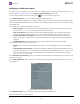
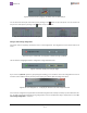
Figure 77: The four audio channel configuration layout
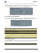
Figure 78: The eight audio channel configuration layout
Theleftsideofanaudiolayoutrepresentstheingestsource,withthenameofthesourcetypedisplayedinthesquare.The
1-8numberedbuttonsrepresentthesourceaudiopins.
Therightsideofanaudiolayoutrepresentstheingestdestination,withthenameofthedestinationsubjecttypedisplayed
inthesquare.The1-8numberedbuttonsrepresentsthedestinationaudiopins.
Theconnectiongraphofthesourcepinstothedestinationpinsisdisplayedinbetween.Forexample,alinkconnectingpin
#1todestinationpin#4meansthatthesourceclipaudiotrack#1willbemappedtothedestinationclipaudiotrack#4.
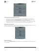
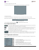
Figure 79: The source (XDCAM) side of the audio layout
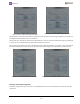
Figure 80: The destination (IPDirector) side of the audio layout
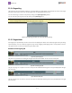
Creating an audio routing configuration
Tomodifyaconfiguration,allyouhavetodoistodraglinksbetweenthesourceanddestinationpins.Thiswillcreatenew
connections.