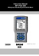
Instruction Manual WP PCD 650 Waterproof Handheld pH/Cond/DO Meter 68X415307 Rev. 0 Feb 07 Technology Made Easy ...
Preface This manual serves to explain the use of the Waterproof Handheld PCD 650 multi parameter Meter. The manual functions in two ways, firstly as a step by step guide to help the user operate the instrument. Secondly, it serves as a handy reference guide. This instruction manual is written to cover many anticipated applications of the PCD 650 Meter. If you have doubts in the use of the instrument, please do not hesitate to contact the nearest Authorised Distributor.
Table of Contents 1. Getting Started ......................................................................................................1 1.1 1.2 1.3 1.4 1.5 1.6 About the Meter...................................................................................................................... 1 Display & Keypad ................................................................................................................... 2 1.2.1 Display Overview...................................................
2.8 2.9 2.10 2.11 2.12 2.13 2.14 TDS Measurement Mode ..................................................................................................... 27 2.8.1 Indicators in TDS measurement mode........................................................................ 27 Salinity Measurement Mode................................................................................................. 28 2.9.1 Indicators in salinity measurement mode ...............................................................
4. Setup Mode ..........................................................................................................71 4.1 About Setup Mode................................................................................................................ 71 4.1.1 Accessing Setup mode (no password protection enabled) ......................................... 71 4.1.2 Accessing Setup mode when password protection enabled....................................... 73 4.1.3 Modifying Setup parameters.............
.2 8.3 Return of Goods ................................................................................................................. 110 Guidelines for Returning Unit for Repair ............................................................................
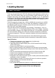
Instruction Manual PCD 650 1. Getting Started 1.1 About the Meter Thank you for purchasing the PCD 650 waterproof multi parameter portable series meter. PCD 650 series meter are micro-controller based instruments and are designed with many user friendly features to measure up to 10 parameters including pH/ mV/ ISE/ Conductivity/ TDS /Salinity/ Resistivity/ DO (%)/ DO (mg/L)/ Temperature. This meter can simultaneously measure and displays up to 2 parameters along with the temperature.
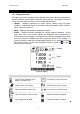
Instruction Manual PCD 650 1.2 Display & Keypad 1.2.1 Display Overview The large monochrome display shows detailed information about measurements, various indicators, annunciators, functions and useful tips. The display consists of 3 main sections when the meter is in the measurement mode: Header – Displays indicators for power source, battery level, pH probe condition, conductivity range of the probe, data transmission mode, real-time clock, user lock/unlock etc.
Instruction Manual PCD 650 Refer calibration mode, measurement mode & setup mode for details on indicators shown in body & footer sections. 1.2.2 Key Functions The keypad consists of: 4 – Function keys (F1, F2, F3 & F4) 4 – Navigation key 1 – Enter key Key Function Selects the function shown (in the display) just above the key. Navigates to next available functions Increment/decrement values in Setup & Calibration modes. Navigates to sub groups in Setup selection screen.
Instruction Manual PCD 650 1.3 Inserting Batteries The meter supports multi -power sources. 1. Four ‘AA’ size 1.5 V alkaline batteries (supplied) or, 2. 9V DC power adapter (Optional in some models). Figure 3 : Battery compartment 1.3.1 Inserting batteries for the first time 1. Use a Phillips screw driver to remove four screws holding the battery cover. 2. Remove the battery cover. 3. Follow the polarity indicated in the battery compartment and insert the batteries. 4.
Instruction Manual PCD 650 1.3.2 Changing batteries subsequently The LCD has battery voltage level indicator. Number of bars indicates the voltage level. See Table 1 for details. When the empty battery indicator starts blinking, it is time to change the batteries. The system time might be automatically reset during the battery change. To prevent that happening, always connect the DC adapter during battery change.
Instruction Manual PCD 650 1.4 Attaching Safety Belt The safety belt provides secured support when you hold the meter on your palm. To attach the safety belt: 1. Use a Phillips screw driver to remove four screws holding the battery cover. 2. Remove the battery cover. 3. Insert the safety belt through the two slots as indicated in the Figure 5. 4. Replace the battery cover onto its original position using the four screws. Note the ▲UP symbol marked on the cover. 5.
Instruction Manual PCD 650 1.5 Connecting Peripherals 1.5.1 Probes (pH/Conductivity/DO) Attach the probes with correct type of connectors as indicated in the figure below. pH Probe (BNC) DO Probe with built in temperature sensor (6-pin Connector) Conductivity Probe with built in temperature sensor (8-pin Connector) Figure 6 : Connecting ph, Cond and DO Probes The PCD 650 meters allows to connect a pH or ISE, DO and a conductivity probe at the same time.
Instruction Manual PCD 650 does not require any polarizing voltage from your meter. The galvanic probe design lets you take measurements immediately – without the typical 15 minute wait of other dissolved oxygen probes. The DO probe comes with an in-built Temperature Compensation for the membrane variation and consists of two parts. The upper part consists of an anode, a cathode, and cable, and lower part consists of a membrane cap, membrane, and electrolyte solution.
Instruction Manual PCD 650 3. Insert the probes into the multi probe holder as shown in Figure 9. After assembling the electrodes into the electrode holder, ensure that the electrode top surfaces are almost level to the edges of the holder. 4. Align the markings on the holder and the cover before locking the cover onto the holder as shown in the diagram. 5. Push up the electrodes backwards to fix the vertical position of the electrodes into the electrode cover.
Instruction Manual PCD 650 1.6 CyberComm 600 Data Acquisition Software 1.6.1 About CyberComm 600 DAS Application The PCD 650 series meters are shipped with a companion software application called CyberComm 600 Data Acquisition Software (DAS). This is a simple, easy to use, Windows® based PCD compatible software application which lets you download your measurement data, calibration reports & stored data from the PCD 650 series meters and save them in your PCD in text (.txt) files.
Instruction Manual PCD 650 Figure 10 : Computer recognizes the meter 4. The ‘Found New Hardware Wizard’ starts automatically. Select ‘Yes, this time only’ option for the first screen. (Figure 11) .Click Next to continue. Figure 11 : First screen of ‘Found New Hardware Wizard’ 5. In the second screen (Figure 12), select ‘Install the software automatically (Recommended)’ and click Next to continue.
Instruction Manual PCD 650 6. Once the wizard completed the installation (Figure 13), click Finish to close the wizard. Figure 13 : ‘Found New Hardware Wizard’ completed 7. In CyberComm 600 application screen, click Find Device button. The screen shows a message “Finding device”.
Instruction Manual PCD 650 (a) (b) Figure 14 : CyberComm finds the meter 4. When CyberComm recognizes the meter it shows “Instrument in Range, click Connect button to establish connection…” Press Connect button. (a) (b) Figure 15 : CyberComm establishing connection with the meter 5. The connection is established and data is transferred.
Instruction Manual PCD 650 Notes: The communication between CyberComm and the meter is unidirectional. The connection is initiated by the meter when you press PRIN key. Once CyberComm finds the meter, press Connect button. Once the connection is established the data is transferred to CyberComm and then the IrDA link is disconnected automatically. IrDA link is disconnected after sending single set of data only if ‘SINGLE’ is selected from System Setup (page 78).
Instruction Manual PCD 650 2. Measurement Mode 2.
Instruction Manual PCD 650 Function Keys available in measurement screen (2nd Group): SETP (F1) Goes to setup mode MEM (F2) Shows stored data in the memory STOR (F3) Stores the currently displayed reading in the memory ESC (F4) Shows 1st Group of functions Function Keys available in measurement screen (3rd Group): REPO(F2) Shows corresponding calibration report (based on selected measurement mode) PRIN (F3) Sends the currently displayed reading to the computer through IrDA.
Instruction Manual 2.2 PCD 650 Taking Measurement 2.2.1 Prepare the meter for measurement Before you start measuring, Make sure you have connected a suitable probe (pH/OPR/ISE), Conductivity probe and DO with in-built ATC to the meter. Make sure the probes are in good working condition & clean. If required, clean (pH/OPR/ISE) probe with clean water, conductivity and DO probe with de-ionized water to remove impurities. For more information on probe’s conditioning refer page 7.
Instruction Manual PCD 650 2.2.5 Automatic Temperature Compensation (ATC) Connect an appropriate probe with built in ATC probe to the meter and select ‘ATC mode’ in the temperature setup (See page 98) for the pH/conductivity/DO reading to be automatically compensated for temperature variations. If you select ‘ATC’ without connecting a probe to the meter, the LCD shows ‘UNDER’ for temperature reading. Figure 18: Under range NOTE: The factory default value for normalization temperature is 25 °C. 2.2.
Instruction Manual PCD 650 2.2.11 pH Calibration points This option allows you to calibrate up to 6 points, depending on the standard buffer selected. Optionally, you can choose to have custom buffers with 2 to 5 points. When completely re-calibrating the meter, the first point of calibration should be one of the following, depending on your choice of standard buffer group. The meter automatically recognizes and calibrates to the standard pH buffer values, which makes pH calibration faster and easier. 2.
Instruction Manual PCD 650 2.2.16 Linear temperature Coefficient The temperature coefficient is a value that reflects the degree to which the conductivity is affected by temperature changes. If you do not know the temperature coefficient of your solution you can determine the correct value using the formula on page 106 “Calculating Temperature Coefficients”. NOTE: Your meter is factory set to a temperature coefficient of 2.1% per °C. 2.2.
Instruction Manual PCD 650 If the pressure comp. is set to ‘DISABLE’, then there would be no compensation for the pressure. The calibration would be done at 100% irrespective of the altitude. Note: This is applicable only for the % Saturation mode. For mg/L or ppm mode, pressure compensation would always be applicable.
Instruction Manual 2.3 PCD 650 Multi Display mode PCD 650 lets you view multi measurement modes at the same time. The measurement modes available for PCD 650 are pH/ mV/ Ion/Conductivity/Salinity/Resitivity/TDS/ DO(%)/DO (mg/L). The parameters being displayed is based on the settings set in the Display Setup. For more information on multi mode setup, refer ‘System Settings – Page 1’ on page 75 to select modes that you would like to appear on the first, second and third row of the display.
Instruction Manual 2.4 PCD 650 pH Measurement Mode 2.4.1 Indicators in pH measurement screen In pH measurement mode, the meter displays pH and temperature reading. 2 3 1 4 5 6 7 8 9 11 10 12 Figure 22 : pH measurement screen Refer item numbers indicated in Figure 22.
Instruction Manual PCD 650 2.5 mV Measurement Mode In mV measurement mode, the meter displays mV and temperature reading. Depending on application, you can connect a suitable ORP probe to the meter or use the pH probe. 2.5.1 Indicators in mV measurement mode 2 1 3 4 5 6 7 Figure 23 : mV measurement screen Refer item numbers indicated in Figure 23.
Instruction Manual PCD 650 2.6 Ion Measurement Mode In Ion measurement mode, the meter displays Ion concentration (in ppm, molar or mg/L) and mV reading. Depending on application, you can connect a suitable Ion Selective Electrode (ISE) to the meter. 2.6.1 Changing unit of measurement By default the measuring unit is ppm. You can select either molar or mg/L in the setup mode (See page 85). 2.6.
Instruction Manual PCD 650 2.7 Conductivity Measurement Mode In conductivity measurement mode, the meter displays conductivity and temperature readings. The LCD shows related information for the conductivity measurement such as temperature compensation mode, stable indicator, probe condition, calibration points, response time of the conductivity probe and conductivity alarm conditions. You can customize or enable/disable some of these indicators in the Setup mode. 2.7.
Instruction Manual PCD 650 2.8 TDS Measurement Mode In TDS measurement mode, the meter displays TDS and temperature reading. 2.8.1 Indicators in TDS measurement mode 2 Note: Lower display shows ‘2Cell’ or ‘4Cell’ when a 2-cell or 4-Cell conductivity probe is connected. 3 1 4 5 6 6 7 8 9 10 11 12 Figure 26 : TDS measurement screen Refer item numbers indicated in Figure 26.
Instruction Manual PCD 650 2.9 Salinity Measurement Mode In Salinity measurement mode, the meter displays salinity and temperature reading. 2.9.1 Indicators in salinity measurement mode 2 Note: Lower display shows ‘2Cell’ or ‘4Cell’ when a 2-cell or 4-Cell conductivity probe is connected. 1 3 4 5 6 7 8 9 6 11 10 12 Figure 27 : Salinity measurement screen Refer item numbers indicated in Figure 27.
Instruction Manual PCD 650 2.10 Resistivity Measurement Mode In Resistivity measurement mode, the meter displays resistivity and temperature reading. 2.10.1 Indicators in Resistivity measurement mode 2 Note: Lower display shows ‘2Cell’ or ‘4Cell’ when a 2-cell or 4-Cell conductivity probe is connected. 1 3 4 5 6 7 9 8 6 11 10 12 Figure 28 : Resistivity measurement screen Refer item numbers indicated in Figure 28.
Instruction Manual PCD 650 2.11 Percentage Saturation (%) Measurement Mode In percentage saturation measurement mode, the meter displays % saturation and temperature reading. The LCD shows related information for the saturation measurement such as temperature compensation mode, stable indicator, barometric pressure, calibration points, probe condition, response time of the DO probe and alarm conditions. You can customize or enable/disable some of these indicators in the Setup mode. 2.11.
Instruction Manual PCD 650 2.12 Concentration (mg/L) (ppm) Measurement Mode In concentration measurement mode, the meter displays concentration and temperature readings. The LCD shows related information for the concentration measurement such as temperature compensation mode, stable indicator, salinity value, probe condition, response time of the DO probe and alarm conditions. You can customize or enable/disable some of these indicators in the Setup mode. 2.12.
Instruction Manual PCD 650 2.13 Transfer Measured Data to Computer (CyberComm) 2.13.1 Sending a single reading from multi measurement mode 1. Make sure that the CURRENT DATA SET parameter is set to ‘SINGLE’ in the System Setup (Refer ‘System Settings – Page 4’ on page 79). 2. Make sure the CyberComm 600 application is up and running (page 12). 3. Make sure the IrDA port of the meter is closer and in-line with IrDA port of the computer. 4.
Instruction Manual PCD 650 10. To stop data transfer, click Disconnect button. 11. To clear the transferred readings from the screen, select the desired row and click Clear Data button. 2.13.2 Sending a single reading from single measurement mode 1. Make sure that the CURRENT DATA SET parameter is set to ‘SINGLE’ in the System Setup (Refer ‘System Settings – Page 4’ on page 79). 2. Make sure the CyberComm 600 application is up and running (page 12). 3.
Instruction Manual 2.13.3 PCD 650 Sending readings continuously in single and multi measurement modes 1. Make sure that the CURRENT DATA SET parameter is set to ‘TIMED’ in the System Setup. Set the time interval at which you wish to send the data to CyberComm (Refer ‘System Settings – Page 4’ on page 79). 2. Make sure the CyberComm 600 application is up and running (page 12). 3. Make sure the IrDA port of the meter is closer and in-line with IrDA port of the computer. 4.
Instruction Manual PCD 650 Note: IrDA link may be disconnected if you move/disorient the IrDA ports during data transfer. Re-align the IrDA ports and press Connect button, to re-establish the connection. 2.13.4 Saving data You can save transferred measurement readings as a text file in your computer. Optionally, these text files can further be analyzed by exporting to spreadsheet application such as Microsoft® Excel. To save data: 1. Once you transferred data to CyberComm, click Disconnect button.
Instruction Manual PCD 650 2.14 Working with Memory functions The PCD 650 has a memory capacity to store up to 500 sets of measurement data. The MEM (F2) function key allows you to view stored data. Optionally, you can transfer this data to a Computer using wireless Infrared connection. 2.14.1 Logging data automatically in meter’s memory 1. Make sure that the Print mode is set to data logging mode in the System Setup and you can also specify the time interval in between each transfer.
Instruction Manual PCD 650 3. Press MEM (F2) key to view stored data. The last stored data entry is shown in the display (Figure 36). The memory location of the currently showing data entry is shown in the top-right corner of the screen. (Figure 36). Figure 36 : Viewing stored data 4. To navigate to a particular memory location, press up or down arrow key to select memory location you intend to navigate to and then press ENTER key. The meter shows the stored data in the memory location you selected. 5.
Instruction Manual PCD 650 9. The CyberComm establishes connection with meter through IrDA and sends the data (Figure 38). The connection stops automatically once the data is transferred. 10. You can save the transferred data to a text file. See ‘Saving data’ section in page 35.
Instruction Manual PCD 650 3. Calibration Mode 3.1 About Calibration PCD 650 series meters are factory calibrated and allows you to measure pH/mV/ion/conductivity/resistivity/TDS/salinity/DO(%)/DO(mg/L). Calibrate to all measurement ranges to ensure the highest accuracy throughout all measurement range. However, it is recommended that, for higher accuracy, you calibrate your meter before you make measurements for the first time.
Instruction Manual PCD 650 The meter automatically recognizes and calibrates to these standard pH buffer values, which makes pH calibration faster and easier. 3.1.3 About Ion Calibration The meter supports Ion calibration up to 8 points with minimum of 2-points. The available 8-points are 0.001, 0.01, 0.1, 1, 10, 100, 1000 & 10000. The meter guides your through the calibration process with on-screen instructions and hints.
Instruction Manual PCD 650 Hence calibration in % Saturation of DO should be carried out first. This is described in the following section. 3.1.6 Prepare the Meter for Calibration Before starting calibration, make sure the meter is in the appropriate measurement mode. For pH Connect the pH probe to the BNC connector of the meter. Be sure to remove the protective electrode storage bottle or rubber cap of the electrode before calibration or measurement.
Instruction Manual PCD 650 Ensure that you use new conductivity standard solutions or sachets during calibration. Do not reuse standard solutions as it may be contaminated and affect the calibration and accuracy of measurements. Use fresh calibration solution each time you calibrate your meter. Keep solutions in a dry and cool environment if possible. For DO(%) and DO (mg/L) Calibration Before starting calibration, make sure you are in the correct measurement mode and in the correct calibration sequence.
Instruction Manual PCD 650 Figure 39 : Login password screen Note: You can enter ‘00000’ (read-only password) if you wish to view the calibration report of the last calibration. You are not allowed to perform calibration when you enter ‘read-only password’. 3. Press up & down arrow keys to enter the first digit of the password and then press NEXT (F3) key to move to the next digit. 4. The next digit is selected. Press up second digit of the password. & down arrow keys to enter the 5.
Instruction Manual PCD 650 3.2 Temperature Calibration The built-in temperature sensor of conductivity and DO probe included with the meter are factory calibrated. The built-in ATC probe of the conductivity cells can be used for temperature readout and compensation of the pH values. DO in mg/L is dependent on temperature, so it is first necessary to calibrate or verify the temperature reading.
Instruction Manual PCD 650 6. The screen shows two readings. The upper display shows the temperature reading of the solution with respect to previous calibration (if any) & lower displays shows the temperature reading of the solution without any calibration (default reading). Use & keys to adjust the upper display to the temperature reading of the thermometer. Note: The meter allows you to adjust the upper display reading up to ±5 ºC or ±9 ºF. (Calibration window) 7.
Instruction Manual PCD 650 3.3 pH Calibration 3.3.1 pH Calibration with a Standard Buffer Make sure you have selected a standard buffer with which you intend to perform pH calibration. Refer ’pH Setup’ section in page 82 for more details of setting buffer types. To start pH Calibration: 1. Switch on the meter and make sure the meter is in pH measurement mode. 2. Press CAL (F2) to start calibration. Note: If the meter is password protected, you will be prompted to enter a password.
Instruction Manual PCD 650 5. Dip the probe in calibration buffer. The tip of the probe must be completely immersed into the solution. Stir the probe gently to create a homogeneous solution. 6. The display shows the pH reading. The meter scans through all the available (un-calibrated) points for the selected buffer group until it finds a close match within its acceptable calibration window. (Refer Specification section in page 99 for calibration window values).
Instruction Manual PCD 650 1. Rinse the electrode in clean water and prepare electrode for calibration. Note: If you wish to completely re-calibrate the meter, you need to clear previous calibration data. Press CLR-C (F2) key to clear previous calibration. The meter shows you confirmation screen. Press ENTER key to confirm deleting previous calibration. 2. Dip the probe in custom calibration buffer. The tip of the probe must be completely immersed into the solution.
Instruction Manual PCD 650 Figure 43: pH Calibration Report Example: In the given pH calibration report (Refer Figure 43), 4-point calibration has been done for USA buffer group (pH 1.68, pH 4.01, pH 7.00 & pH 12.45). The slope is 93 for the range enveloped from pH 1.68 to pH 4.01. The slope is 88 for the range enveloped from pH 4.01 to pH 7.00. The slope is 94 for the range enveloped from pH 7.00 to pH 12.45 where pH 10.01 calibration point has been skipped.
Instruction Manual PCD 650 Number of bars in the indicator shows the slope value: Number of Bars Average Slope of the pH Probe 4 Above 90% 3 90% to 80% 2 80% to 70% 1 Below 70% 50
Instruction Manual PCD 650 3.4 mV Calibration Use a standard ORP solution of known value for calibration. You need to calibrate only 1-point. 1. Switch on the meter. Make sure the meter is in mV measurement mode. 2. Press CAL (F2) to go to calibration mode. Note: If the meter is password protected, you will be prompted to enter a password. Refer ‘Accessing Calibration mode when password protection enabled’ in page 42. 3.
Instruction Manual PCD 650 Note: The function of the keys available on the mV calibration/ report screen is same as previously described in pH calibration with a userdefined buffer section (page 48). 3.4.1 mV Calibration Report Calibration report gives you information on calibration. It includes date & time on which the last calibration was done and the offset. To View calibration Report: 1.
Instruction Manual PCD 650 3.5 Ion Calibration Use standard solutions of 0.001, 0.01, 0.1, 1, 10, 100, 1000 & 10000 ppm for calibration. You need to calibrate minimum of 2-points. Follow the instruction in ‘Prepare the meter for measurement’ section in page 40. 1. Switch on the meter. Make sure the meter is in Ion measurement mode. 2. Press CAL (F2) to go to calibration mode. Note: If the meter is password protected, you will be prompted to enter a password.
Instruction Manual PCD 650 6. Allow time for the reading to stabilize. Press ENTER key to confirm the selected point. The meter flashes the upper display to acknowledge the first point calibration. 7. The upper display shows the next calibration point. 8. Rinse the ISE with clean water. Place it in the next calibration solution and follow the steps 4 through 6 to calibrate other points.
Instruction Manual PCD 650 3.6 Conductivity Calibration 3.6.1 Manual Calibration Make sure you have selected a standard solution with which you intend to perform conductivity calibration, refer page 86 for more details of setting solution types. To start manual Calibration for conductivity: Following is the procedure for single point calibration: 1. Switch on the meter and make sure the meter is in conductivity measurement mode. 2. Dip the probe into the calibration standard.
Instruction Manual PCD 650 Note: If you wish to completely re-calibrate the meter, you need to clear previous calibration data. Press CLR-C (F2) key to clear previous calibration. The meter shows you confirmation screen. Press ENTER key to confirm deleting previous calibration. Figure 49 : Conductivity calibration Screen 7.
Instruction Manual PCD 650 The following screen is displayed after cell adjustment screen, if you have selected ‘Auto’ in Calibration mode and ‘MULTI’ in Calibration Point: Figure 50 : Conductivity calibration Screen-Auto 1. Rinse the electrode in de-ionized water and prepare electrode for calibration. Refer ‘Prepare the meter for measurement’ section in page 40. Note: If you wish to completely re-calibrate the meter, you need to clear previous calibration data.
Instruction Manual PCD 650 Note: If the user has selected ‘SINGLE’ point calibration and ‘AUTO’ calibration mode, the meter will go to measurement mode after step 4. 3.6.3 Calibration Report Calibration report gives you detailed information on calibration. It includes date & time, calibration points, range, factor and cell constant. To View calibration Report: 1.
Instruction Manual PCD 650 3.7 Resistivity Calibration Use a standard solution of known value for calibration. Use the single-point standardization option to measure samples that close in value and multi-point standardization to measure wide range of samples. 1. Switch on the meter. Make sure the meter is in resistivity measurement mode. 2. Press CAL (F2) to go to calibration mode. 3.
Instruction Manual PCD 650 Note: The function of the keys available on the resistivity cell constant/calibration/ report screen is same as previously described in conductivity calibration. 8. Rinse the probe with de-ionized water. Place it in the next solution and follow the steps 2 to 7 to calibrate other points, if ‘MULTI’ point calibration is selected. 9. Press ESC (F4) to go to measurement mode. The meter shows the resistivity reading of the solution in measurement mode. 3.7.
Instruction Manual PCD 650 3.8 Salinity Calibration Use a standard solution of known value for calibration. Use the single-point standardization option to measure samples that close in value and multi-point standardization to measure wide range of samples. 1. Switch on the meter. Make sure the meter is in salinity measurement mode. 2. Press CAL (F2) to go to calibration mode. Note: If the meter is password protected, you will be prompted to enter a password.
Instruction Manual PCD 650 Note: The function of the keys available on the salinity cell constant/calibration/ report screen is same as previously described in conductivity calibration. 8. Rinse the probe with de-ionized water. Place it in the next solution and follow the steps 2 to 7 to calibrate other points, if ‘MULTI’ point calibration is selected. 9. Press ESC (F4) to go to measurement mode. The meter shows the salinity reading of the solution in measurement mode. 3.8.
Instruction Manual PCD 650 3.9 TDS Calibration You can commence calibration in the TDS mode by using the conductivity calibration method and after setting the correct TDS factor. For more information regarding TDS conversion factor determination, please refer to page 106. For the rest of the calibration process, follow steps as mentioned in the section of manual calibration on page 55. Use a standard solution of known value for calibration.
Instruction Manual PCD 650 Note: The function of the keys available on the TDS cell constant/calibration/ report screen is same as previously described in conductivity calibration. 8. Rinse the probe with de-ionized water. Place it in the next solution and follow the steps 2 to 7 to calibrate other points, if ‘MULTI’ point calibration is selected. 9. Press ESC (F4) to go to measurement mode. The meter shows the TDS reading of the solution in measurement mode. 3.9.
Instruction Manual PCD 650 3.10 DO Calibration in % Saturation Mode (with ATC) The PCD 650 can be calibrated quickly and easily in air. In % Saturation, the meter is able to perform either a one point calibration or a 2 point calibration. For one point calibration, it is recommended that you perform a 100% Saturation calibration in saturated air. If you opt for 2 point calibration, you can calibrate for 100% Saturation in saturated air and 0% Saturation using a zero oxygen solution.
Instruction Manual PCD 650 6. Press ENTER key to confirm the calibration. The meter automatically calibrates to 100% air saturation and returns to the measurement mode. Note: If you wish to completely re-calibrate the meter, you need to clear previous calibration data. Press CLR-C (F2) key to clear previous calibration. The meter shows you confirmation screen. Press ENTER key to confirm deleting previous calibration.
Instruction Manual PCD 650 3.10.2 To calibrate 0% saturation Figure 60 : 0% saturation calibration Screen 1. Press MODE key to select % Saturation mode. 2. Immerse the DO probe in 0% solution. Stir gently to create a homogenous solution. 3. Press CAL key to calibrate the meter. The meter shows ‘Dissolved O2 Calibration-Rinse Electrode’ screen [Figure 48(a)] for few seconds to prompt user to rinse electrode with de-ionized water before calibration. 4.
Instruction Manual PCD 650 To View calibration Report: 1. From % saturation measurement mode, press left or right arrow key to navigate to other available functions until you see REPO function in the LCD. 2. Press REPO (F2) key. The calibration report is shown in the display. 3. Press PRIN (F2) to transfer the calibration report to computer through IrDA. (Refer page 37 to print data).
Instruction Manual PCD 650 3.11 DO Calibration in mg/L or ppm Concentration Mode The amount of oxygen dissolved in a liquid will depend on its temperature, pressure and salinity. It is therefore very important to set temperature and salinity correctly before attempting to do a calibration. The PCD 650 is capable of measuring barometer pressure with its built-in pressure sensor. In the event, the pressure reading is inaccurate, you can calibrate the value from the Setup menu. 1. Switch on the meter.
Instruction Manual PCD 650 Figure 63 : Concentration calibration Note: The function of the keys available on the concentration calibration/ report screen is same as previously described in saturation calibration. 3.11.1 Concentration Calibration Report Calibration report gives you information on calibrated temperature and calibration at pressure and salinity. It includes date & time on which the last calibration was done and the offset. To View Concentration Report: 1.
Instruction Manual PCD 650 4. Setup Mode 4.1 About Setup Mode The setup mode lets you configure various parameters & settings of the meter. You can choose to password-protect your settings, so that other users who may use the meter will not be able to change the settings.
Instruction Manual PCD 650 Function Keys available in setup key function screen: To select individual setup ENTER To select or confirm the selection. NEXT-P To navigate to next page. NEXT To go to next parameter without saving the changed parameter. ESC To go back to measurement mode. 4. Press ENTER key to select Setup Selection screen. 5. Press up or down arrow key to go to required setup sub-group. 6. Press ENTER key to select the currently shown sub-group.
Instruction Manual PCD 650 4.1.2 Accessing Setup mode when password protection enabled Follow the steps below to access the setup mode, when password protection is enabled. 1. Switch on the meter. The meter goes to measurement mode. 2. Press right arrow key to navigate to other functions on the right-side of LCD. 3. Press SETP (F1) to go to Setup mode. Login password screen appears (Figure 67). The meter expects the 5-digit password specified in system setup.
Instruction Manual PCD 650 4.1.3 Modifying Setup parameters Follow the steps below to modify setup parameters, when you enter a setup sub-group. 1. Press NEXT (F3) key to select individual setup parameters sequentially. 2. Press (Up) or parameter. (Down) arrow key to change the value of a selected 3. Once you changed a value: • Press ENTER key to save the change, or • Press NEXT (F3) key to go to the next parameter without saving the changed parameter. 4.
Instruction Manual PCD 650 4.2 System Setup System setup sub-group allows you to configure general settings of the meter. The settings are displayed in 6 pages. Press NEXT-P (F2) and PREV-P (F1) to navigate through these pages. 4.2.1 System Settings – Page 1 Figure 68: System Settings - Page 1 Parameter STABLE Indicator Stability Criteria Auto Hold Description ENABLE - The meter displays ‘Stable’ indicator in the measurement screen as per the ‘STABLE CRITERIA’ defined below.
Instruction Manual PCD 650 Tem. Display from Allows to select temperature from pH/COND/DO probes to display in multi measurement screen. Display setting:- For PCD 650-pH/COND->DO Allows to select multi modes that you would like to be displayed on the 1st, 2nd and 3rd row of the measurement screen after calibration.
Instruction Manual PCD 650 4.2.2 System Settings – Page 2 Figure 69 : System Settings - Page 2 This page allows you to set the date & time of the meter.
Instruction Manual PCD 650 4.2.3 System Settings – Page 3 Figure 70 : System Settings - Page 3 This page allows you to set auto-off and back light related parameters. Parameter Description ENABLE – Turns off the meter automatically if no key is pressed for the time period specified in ‘ON TIME’ below. DISABLE – Does not turns off the meter automatically After the last key is pressed, no. of minutes the meter should wait before automatically shuts down the meter.
Instruction Manual PCD 650 4.2.4 System Settings – Page 4 Figure 71: System Settings - Page 4 This page allows you to set wireless serial data communication related parameters. Parameter Print Mode Data Format Current Data Set Interval (3 Sec Step) Fixed Setting Description IrDA – Sets serial data communication protocol to IrDA LED – Sets serial data communication protocol to RS232C MEM- Logs data to meter’s memory.
Instruction Manual PCD 650 4.2.5 System Settings – Page 5 This page allows you to enable password protection for the setup mode & calibration mode. Figure 72 : System Settings - Page 5 When you enable password protection, the meter prompts to enter the password whenever you try to access the Setup or Calibration mode. (See Figure 67: Login password screen).The meter does not allow you to edit setup parameters or perform a new calibration unless you enter the correct password.
Instruction Manual PCD 650 Important: 1. Please memorize the password that you have entered after enabling the password protection because without entering password, neither you can disable the password protection or reset the meter to factory defaults. However, if the user forgets his password, he can contact the nearest distributor or Eutech Instruments/Oakton Instruments to request for meter password. This would be unique to each instrument and would be tied to the serial number of the unit. 2.
Instruction Manual PCD 650 4.3 pH Setup pH setup sub-group allows you to configure pH measurement & calibration related settings of the meter. The settings are displayed in 2 pages. Press NEXT-P (F2) and PREV-P (F1) to navigate through these pages. 4.3.1 pH Settings – Page 1 Figure 74: pH Settings - Page 1 This page allows you to set pH measurement & calibration related settings of the meter.
Instruction Manual PCD 650 4.3.2 pH Settings – Page 2 Figure 75: pH Settings - Page 2 Parameter Description pH Calibration Due Specify number of days for the pH calibration alarm. The meter shows CAL DUE indicator after calibration due days are passed from the last calibration date. Available range: 0 to 30 pH Resolution Sets the resolution for pH measurement Available range: 0.1, 0.01, 0.001 Factory Default 5 Days 0.
Instruction Manual PCD 650 4.4 mV setup (no settings available) No settings are available for mV. Figure 76: mV Setting Page Press ESC (F4) to go to measurement mode.
Instruction Manual PCD 650 4.5 Ion Setup Ion setup sub-group allows you to configure Ion measurement & calibration related settings of the meter. 4.5.1 Ion Settings Page Figure 77: Ion Settings Page Parameter Ion unit ) Press Description Sets the unit of measurement for Ion. Available units: ppm, molar and mg/L (Up) or Factory Default ppm (Down) arrow key to change the value of a selected parameter.
Instruction Manual 4.6 PCD 650 Conductivity Setup Conductivity setup screen present many options to control the operating parameters, which can be controlled and set from the conductivity setup screen. The settings are displayed in 2 pages. Press NEXT-P (F2) and PREV-P (F1) to navigate through these pages. 4.6.
Instruction Manual PCD 650 Note: 1. If pure water coefficient is ‘ENABLE’, the meter will apply pure water compensation automatically below 2 µS and switch back to linear compensation for above 2 µS. 2. If pure water coefficient is ‘DISABLE’, Lnr Temp Coefficient applies throughout the measurement. 4.6.2 Conductivity Settings – Page 2 Figure 79 : Conductivity Settings - Page 2 This page allows you to set alarm limits for the conductivity measurement mode.
Instruction Manual PCD 650 4.7 TDS Setup TDS setup screen present many options to control the operating parameters, which can be controlled and set from the TDS setup screen. The settings are displayed in 2 pages. Press NEXT-P (F2) and PREV-P (F1) to navigate through these pages. 4.7.
Instruction Manual PCD 650 4.7.
Instruction Manual PCD 650 4.8 Salinity Setup Salinity setup screen present many options to control the operating parameters, which can be controlled and set from the salinity setup screen. The settings are displayed in 2 pages. Press NEXT-P (F2) and PREV-P (F1) to navigate through these pages. 4.8.1 Salinity Settings – Page 1 Figure 82: Salinity Settings - Page 1 This page allows you to set operating parameters for salinity measurement.
Instruction Manual PCD 650 This page allows you to set alarm limits for the salinity measurement mode: Parameter Alarm Set Points Hi ppm Lo ppt Description Set alarm limits for the salinity measurement mode: ENABLE – The measurement screen shows HI or LO alarm indicators when the meter reading is above ‘HI alarm value’ or below ‘LO alarm value’ specified in HI & LO ppm parameters (below) DISABLE – HI and LO alarms are not shown in the LCD Specify Hi alarm value here.
Instruction Manual PCD 650 4.9 Resistivity Setup Resistivity setup screen present many options to control the operating parameters, which can be controlled and set from the resistivity setup screen. The settings are displayed in 2 pages. Press NEXT-P (F2) and PREV-P (F1) to navigate through these pages. 4.9.1 Resistivity Settings – Page 1 Figure 84: Resistivity Settings - Page 1 This page allows you to set operating parameters for resistivity measurement mode.
Instruction Manual PCD 650 This page allows you to select alarm limits for resistivity measurement mode. Parameter Alarm Set Points Hi Ω Lo Ω ) Press Description Set alarm limits for the resistivity measurement mode: ENABLE – The measurement screen shows HI or LO alarm indicators when the meter reading is above ‘HI alarm value’ or below ‘LO alarm value’ specified in HI & LO Ω parameters (below) DISABLE – HI and LO alarms are not shown in the LCD Specify Hi alarm value here.
Instruction Manual PCD 650 4.10 O2 % - DO Saturation Setup DO saturation (%) setup screen present many options to control the operating parameters, which can be controlled and set from the DO setup screen. The settings are displayed in 2 pages. Press NEXT-P (F2) and PREV-P (F1) to navigate through these pages. 4.10.
Instruction Manual PCD 650 4.10.2 DO (%) – Page 2 Figure 87: DO (%) - Page 2 This page allows you to set alarm limits for the DO saturation measurement mode. A visual alarm symbol will appear on the screen, if the DO value of the measurement is outside of the boundaries set by the minimum and maximum limits.
Instruction Manual 4.11 PCD 650 O2 mg/L (ppm) – DO Concentration Setup DO Concentration (mg/L) setup screen present many options to control the operating parameters, which can be controlled and set from the DO setup screen. The settings are displayed in 2 pages. Press NEXT-P (F2) and PREV-P (F1) to navigate through these pages. 4.11.
Instruction Manual 4.11.2 PCD 650 DO (mg/L) – Page 2 Figure 89: DO (mg/L) – Page 2 This page allows you to set alarm limits for the DO concentration mode. A visual alarm symbol will appear on the screen, if the DO value of the measurement is outside of the boundaries set by the minimum and maximum limits.
Instruction Manual PCD 650 4.12 Temperature Setup Temperature setup sub-group allows you to configure temperature measurement & calibration related settings of the meter. 4.12.1 Temperature Setting Page Figure 90 : Temperature Settings Page Parameter Unit Mode Description Sets the unit of measurement for temperature. Available units: ºC and ºF Sets the temperature compensation mode.
Instruction Manual PCD 650 5. Technical Specifications Model PCD 650 meter pH Range Resolution Relative Accuracy -2.000 to 20.000 pH 0.1/0.01/0.001 pH ± 0.002 pH + 1 LSD 1 (offset) to 6 points 15 User configurable (up to 30 days) User configurable Yes USA : 1.68, 4.01, 7.00, 10.01, 12.45 NIST: 1.68, 4.01, 6.86, 9.18, 12.45 DIN : 1.09, 3.06, 4.65, 6.79, 9.23, 12.74 PWB : 4.10, 6.97 No. of Calibration points No.
Instruction Manual PCD 650 1 0.050uS to 2.000uS 0.01uS* 1% of FS No 2 2.000uS to 9.990 uS 10.00uS to 99.99uS 100.0uS to 300.0uS 0.01uS* 0.01uS 0.1uS 1% of FS 1% of FS 1% of FS 84.00uS 3 300.0uS to 999.9uS 1.000mS to 4.000mS 0.1uS 0.001mS 1% of FS 1% of FS 1.413mS 4 4.000mS to 9.999mS 10.00mS to 40.00mS 0.001mS 0.01mS 1% of FS 1% of FS 12.88mS 40.00mS to 99.99mS 100.0mS to 500.0mS 0.01mS 0.1mS 1% of FS 1% of FS 111.8mS 5 * Display resolution is 0.001 TDS at TDS factor 1.
Instruction Manual PCD 650 500.0KΩ to 999.9KΩ 0.1KΩ 1% of FS 4 100.0KΩ to 500.0KΩ 10.00KΩ to 99.99KΩ 3.333KΩ to 9.999KΩ 0.1Ω 0.01Ω 0.001Ω 1% of FS 1% of FS 1% of FS 3 1.000KΩ to 3.333KΩ 250.0Ω to 999.9Ω 0.001Ω 0.1Ω 1% of FS 1% of FS 2 100.0Ω to 250.0Ω 25.00Ω to 99.99Ω 0.1Ω 0.01Ω 1% of FS 1% of FS 1 10.00Ω to 25.00Ω 2.000Ω to 9.990Ω 0.01Ω 0.01Ω* 1% of FS 1% of FS * Display resolution is 0.
Instruction Manual PCD 650 6. Accessories 6.1 Replacement Accessories Eutech Instruments Product Description Rubber Boot for 600 series meters 100-240VAC Power Adapter 6.
Instruction Manual PCD 650 35641-51 General Purpose Plastic-Body, Double Junction, Ag/AgCl pH electrode (1m Cable) General Purpose Plastic-Body, 3-in-1,pH/Temp Ag/AgCl pH electrode (1m Cable) 2-cell Electrode with ATC, cell constant K=1.0 (OKCONSEN9103J, 3m cable) 2-cell Electrode with ATC, cell constant K=1.0 35408-52 4-cell Electrode with ATC, cell constant K=0.3 35408-56 2-cell Electrode with ATC, cell constant K=10.0 35408-54 2-cell Electrode with ATC, cell constant K=0.
Instruction Manual PCD 650 7. APPENDIX 7.1 Conductivity theory Conductance is a quantity associated with the ability of primarily aqueous solutions to carry an electrical current, I, between two metallic electrodes when a voltage E is connected to them. Though water itself is a rather poor conductor of electricity, the presence of ions in the water increases its conductance considerably, the current being carried by the migration of the dissolved ions.
Instruction Manual PCD 650 The PCD 650 series meter not only measures conductivity readings from micro or milli Siemens but also reads resistivity (Ohms, kOhms and MOhms), TDS (ppm and ppt), and salinity (ppt). The salinity scale which ranges from 0 to 80 ppt is a measure of all salts, not just sodium chloride. This scale was originally devised for seawater, and is based on seawater at 15 degrees Centigrade has a conductivity equivalent to that of a potassium chloride solution of a known concentration.
Instruction Manual PCD 650 7.2 Calculating TDS Conversion Factor You can calibrate your meter using TDS calibration standard solutions. The calibration standard only needs to give the TDS value at a standard temperature such as 25 °C. To determine the conductivity-to-TDS conversion factor use the following formula: Factor = Actual TDS ÷ Actual Conductivity @ 25 °C Definitions: Actual TDS: Value from the solution bottle label or as a standard you make using high purity water and precisely weighed salts.
Instruction Manual PCD 650 7.4 Dissolved Oxygen Probe 7.4.1 Dissolved Oxygen Principle The probe is a galvanic measuring element which produces an output proportional to the oxygen present in the medium in which it is placed. The galvanic probe design lets you take measurements immediately – without the typical 15 minute wait of other dissolved oxygen probes. The probe consists of two parts: • An upper part consisting of an anode, a cathode, and cable.
Instruction Manual 7.4.3 PCD 650 Membrane Housing Replacement Replacement of the membrane cap housing/ membrane is required only when you cannot calibrate the probe, or if the membrane is damaged. Typical membrane damages are punctures or wrinkles caused during measurements or cleaning. Your new DO probe comes with replacement membrane housing. To order more replacement membrane housing, see the “Accessories” section page. To replace the membrane cap (with pre-installed membrane) 1.
Instruction Manual PCD 650 2. Hold the probe under hot running water and brush away the white oxide on the cylindrical anode with a stiff plastic brush – do not use metal cleaning material. 3. If the cathode has any deposits, remove them with a light scouring powder. Do not polish the cathode. 4. Using the installation tool, unscrew and remove the membrane lock from the membrane cap. See Figure 93 on the following page. 5. Remove the membrane and O-ring. Discard both. 6.
Instruction Manual PCD 650 8. General Information 8.1 Warranty Eutech Instruments supplies this meter with a 3-year warranty and 6-month warranty for electrode against manufacturing defects from the date of purchase. If repair or adjustment is necessary and has not been the result of abuse or misuse within the designated period, please return – freight pre-paid – and correction will be made without charge.
For more information on Eutech Instruments’/ Oakton Instruments’ products, contact your nearest distributor or visit our website listed below: Oakton Instruments P.O Box 5136, Vernon Hills, IL 60061, USA Tel: (1) 888-462-5866 Fax: (1) 847-247-2984 E-mail: info@4oakton.com Web-site: www.4oakton.com Eutech Instruments Pte Ltd. Blk 55, Ayer Rajah Crescent, #04-16/24 Singapore 139949 Tel: (65) 6778 6876 Fax: (65) 6773 0836 E-mail: marketing@eutechinst.com Web-site: www.eutechinst.