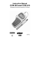
Instruction Manual CON 400 and CON 410 Waterproof Hand-held Conductivity/TDS Meter Technology Made Easy ...
Preface This manual serves to explain the use of the Waterproof CON 400/410 hand-held meters. It functions in two ways, firstly as a step by step guide to help you to operate the meter. Secondly, it serves as a handy reference guide. It is written to cover as many anticipated applications of the Waterproof CON 400/410 meters as possible. If there are doubts in the use of the meter, please do not hesitate to contact the nearest Authorised Distributor.
TABLE OF CONTENTS 1 INTRODUCTION .............................................................................................. 1 2 DISPLAY AND KEYPAD FUNCTIONS............................................................. 2 2.1 2.2 3 PREPARATION ................................................................................................ 4 3.1 3.2 3.3 4 DISPLAY .................................................................................................................... 2 KEYPAD ............
8 PROBE CARE AND MAINTENANCE............................................................. 40 9 TROUBLE SHOOTING GUIDE....................................................................... 41 10 ERROR MESSAGES.................................................................................. 42 11 SPECIFICATIONS ...................................................................................... 43 12 ACCESSORIES .....................................................................................
Instruction Manual 1 CON 400/410 INTRODUCTION Thank you for selecting the CON 400/410 waterproof portable meter. This meter is a microprocessor-based instrument that is designed to be user-friendly and allow one-hand operation. It has a built-in real time clock, expanded memory, and many other user-friendly features, all of which are accessible through the membrane keypad.
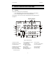
Instruction Manual 2 CON 400/410 DISPLAY AND KEYPAD FUNCTIONS 2.1 Display The LCD has a primary and secondary display. • The primary display shows the measured conductivity or TDS reading. • The secondary display shows the measured temperature. The display also shows error messages, keypad functions and program functions. See Figure 1. Primary Display 1 SETUP 20 19 READY HOLD ON 18 OFF 3 4 CAL MEM 2 MEAS -8.8.8.
Instruction Manual 2.2 CON 400/410 Keypad The large membrane keypad makes the instrument easy to use. Each button, when pressed, has a corresponding graphic indicator on the LCD. See Figure 2. Some buttons have several functions depending on its mode of operation. Key Function ON/OFF Powers on and shuts off the meter. When you switch on the meter, the meter starts up in the mode that you last switched off from.
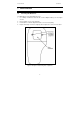
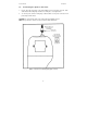
Instruction Manual 3 3.1 CON 400/410 PREPARATION Inserting the Batteries Four AAA batteries are included with your meter. 1. Use a Philips screwdriver to remove the two screws holding the battery cover. See Figure 3 below. 2. Remove battery cover to expose batteries. 3. Insert batteries. Follow the diagram inside the cover for correct polarity. 4. Replace the battery cover into its original position using the two screws removed earlier.
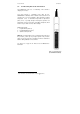
Instruction Manual 3.2 CON 400/410 Conductivity Electrode Information The CON400/410 meter uses a conductivity / TDS cell with a sturdy 6-pin connector. Your meter includes a conductivity probe (Part No: ECCONSEN91W / 35608-50) Ultem / Stainless Steel cells with a cell constant of K = 1.0. This conductivity / TDS cell features a built-in temperature sensor for Automatic Temperature Compensation (ATC).
Instruction Manual 3.3 1. CON 400/410 Connecting the probe to the meter Line up the notch and 6 pins on the meter with the holes in the 6-pin connector. Push down and turn the locking ring clockwise to lock into place. See figure below. 2. To remove probe, turn the locking ring counterclockwise on the probe connector. Pull probe away from the meter. CAUTION: Do not pull on the probe cord or the probe wires might disconnect. NOTE: Keep connectors clean. Do not touch connector with soiled hands.
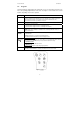
Instruction Manual 4 CON 400/410 CALIBRATION 4.1 Important Information on Meter Calibration Your meter has five measuring ranges. You can calibrate one point in each of the measuring ranges (up to five points). If you are measuring values in more than one range, make sure to calibrate each of the ranges you are measuring. To view current calibration points, see SETUP section Program 2.0 on page 28. The following table lists the corresponding conductivity and TDS ranges.
Instruction Manual 4.2 CON 400/410 Preparing the Meter for Calibration Before starting calibration, make sure you are in the correct measurement mode. When you switch on the meter, the meter begins with the units you shut it off in. For best results, select a standard value close to the sample value you are measuring. Alternatively use a calibration solution value that is approximately 2/3 the full-scale value of the measurement range you plan to use.
Instruction Manual 4.3 CON 400/410 Temperature Calibration MEAS 1413 Your probe features a built-in temperature sensor. The temperature sensor is factory calibrated. Calibrate your 22.3 sensor only if you suspect temperature errors that may have occurred over a long period of time or if you have a replacement probe. ATC CAL 1413 µS °C 22.3 ATC DE MO CAL 22.3 22.3 MI °C ATC MR CAL * If the ATC indicator does not light up, see Program P4.3 22.0 to switch it on. 22.
Instruction Manual 4.4 CON 400/410 Conductivity Calibration The CON 400 and CON 410 meters are capable of up to 5-point conductivity calibration at one point per conductivity range (0.00 - 19.99 µS; 0.0 - 199.9 µS; 0 1999 µS; 0.00 - 19.99 mS; 0.0 - 199.9 mS). All new calibration data will over-ride existing stored calibration data for each measuring range calibrated. Calibrating for Conductivity: 1. If necessary, press the MODE key to select conductivity mode. 2.
Instruction Manual CON 400/410 NOTES: When entering calibration mode, the meter displays the factory default value. If the meter was previously calibrated, the display may seem to “jump” to the factory default value when switching from measurement to calibration mode. This is expected. To exit from Conductivity calibration mode without confirming calibration, DO NOT press the ENTER key in step 6. Press CAL/MEAS instead.
Instruction Manual 4.5 CON 400/410 TDS Calibration 4.5.1 Calibrating for TDS directly For CON 410 meter only The factory default setting for the TDS conversion factor is 0.50. If your solution has a different TDS factor, you can improve calibration accuracy by setting the TDS factor prior to calibration. See page 33 for directions. 1. If necessary, press the MODE key to select TDS mode. 2.
Instruction Manual 4.5.2 CON 400/410 Calibration with Conductivity Standard and TDS factor For CON 410 meter only The concentration of salts dissolved in solution increases the conductivity of that solution. This relationship varies from salt to salt and is roughly linear over a given range for a given salt. The TDS conversion factor is the number used by the meter to convert from conductivity to TDS. Instead of calibrating for TDS directly (described in Section 4.5.
Instruction Manual CON 400/410 From measurement mode 1. Press Setup key to enter Set Up mode. SETUP 2. cof Press the S and T keys to scroll through subgroups until you view parameter P4.0. p 4.0 See Figure 9. MI 3. a value and the lower display shows “tdS”. 4. MR Press the ENTER key again. The upper display shows SETUP ppt ppm Calculate the TDS factor of your solution. See Addendum 2 on page 46 for information on how to p 4.4 calculate the TDS factor. 5.
Instruction Manual 5 CON 400/410 MEASUREMENT This meter is capable of taking measurements with automatic or manual temperature compensation. Factory default is set with automatic temperature compensation (ATC) on. 5.1 Automatic Temperature Compensation For automatic temperature compensation (ATC) simply plug the conductivity/TDS probe into the meter (see page 6 for directions). The ATC indicator will light on the LCD.
Instruction Manual 5.2 CON 400/410 Manual Temperature Compensation IMPORTANT: For manual compensation, you must deactivate the automatic temperature compensation feature. 5.2.1 Selecting Manual Temperature Compensation To select between Automatic Temperature Compensation (ATC) and Manual Temperature Compensation in the SETUP program P4.3. Meter default is ATC on. P4.0 Configuration Setup From measurement mode 1) Press SETUP key to enter Set Up mode.
Instruction Manual 5.2.2 CON 400/410 Setting a manual temperature compensation value To use manual temperature compensation, you need to manually enter the temperature value of your process into the meter. You can select any temperature between 0 and 100 °C (32 to 212 °F). Default value is 25 °C. To select a manual temperature compensation value 1. Switch the meter on. Press the MODE key to select measurement mode. 2. If necessary, select ATC off as described in section 5.2.1 on page 16.
Instruction Manual 5.3 CON 400/410 Taking Measurements To take readings: 1. Rinse the probe with DI or distilled water before use to remove any impurities adhering to the probe body. Shake or air dry. To avoid contamination or dilution of your sample, rinse probe with a small volume of your sample liquid. 2. Press ON to switch on meter and the MEAS Figure 10 - During measurement annunciator appears on the top center of the LCD. 3. Dip the probe into the sample.
Instruction Manual 5.4 CON 400/410 Using Manual Ranging Function Your meter automatically selects the range in which your readings appear. The manual ranging function lets you select the specific range (and corresponding resolution) that you want to work in: CON 400 and CON 410 meters: CON 410 meter: 1. 0.00 --- 19.99 µS 2. 0.0 --- 199.9 µS 2. 0.0 --- 99.9 ppm 3. 0 --- 1999 µS 3. 0 --- 999 ppm 1. 0.00 --- 9.99 ppm 4. 0.00 --- 19.99 mS 4. 0.00 --- 9.99 ppt 5. 0.0 --- 199.9 mS 5.
Instruction Manual 5.5 CON 400/410 HOLD Function This feature lets you freeze the display for a delayed observation. HOLD can be used any time in MEAS mode. 1. To hold a measurement, press the HOLD key while in measurement mode. “HOLD” will appear on the display. 2. To release the held value, press the HOLD again. Continue to take measurements. Figure 13 - HOLD function NOTE: • • This meter shuts off automatically after 20 minutes of nonuse (without key press).
Instruction Manual 6 6.1 CON 400/410 MEMORY AND DATA INPUT FUNCTIONS Memory Input Your meter stores up to 50 sets of data. Data sets include conductivity, temperature, date and time. To store a reading: 1. During any measurement function (MEAS), press MI/S key to input any data into the memory. 2. MEM, “Sto” and memory number will flash. The meter then returns to measurement mode. 3. If necessary, measure the next sample solution and press MI/S key to input the next data into the memory.
Instruction Manual 6.2 CON 400/410 Memory Recall This function recalls the previous readings stored in the memory. You can access MR from the measurement mode only. Memory recall is in "Last In First Out" order. To recall readings: 1. Press the MR/T key once to retrieve the last reading stored. The memory location screen – MEM, “Loc” and the memory number – will flash on the display. 2. Press the ENTER key to recall the reading stored under that memory number. 3.
Instruction Manual 7 CON 400/410 ADVANCED SETUP FUNCTIONS The advanced setup mode lets you customised your meter’s preferences and defaults. The Waterproof CON400 / CON410 meters features different sub-groups that organise setup parameters. The sub-groups are: 1. P1.0: Memory clear (CLr) 2. P2.0: Viewing calibration data (CAL) 3. P3.0: Viewing electrode data (ELE) 4. P4.0: Unit configuration (COF) 5. P5.0: Temperature (tPr) 6. P6.0: Selecting cell constant (CEL) 7. P7.
Instruction Manual CON 400/410 Figure 22 - Overall view of SETUP programs - 24 -
Instruction Manual 7.1 CON 400/410 Advanced SETUP Mode Overview Press the SETUP key to enter Set up mode. Press the MI/S or MR/T keys to scroll through sub groups. Press ENTER key to enter a particular parameter. See Addendum 4 on page 48 for a table of meter factory default settings. P1.0: Memory clear P1.0 Clear all stored readings P2.0: Viewing previous calibration data P2.1 First range calibration point P2.2 Second range calibration point P2.3 Third range calibration point P2.
Instruction Manual CON 400/410 P5.0: Temperature P5.1 Adjusting temperature coefficient P5.2 Adjusting normalization temperature P6.0: Selecting cell constant P6.1 Selecting cell constant: K = 1.0, 10, or 0.1 P7.0: Setting Clock • Setting Year • Setting Date (month/day) • Setting Time (hour / minute / second) P8.0: Reset to factory defaults P8.
Instruction Manual 7.2 CON 400/410 P 1.0: Memory Clear (CLr) Use this parameter to clear all stored memory values when you need to store a new series of values. This lets you avoid confusing the old values with the new ones. NO is the default setting. NOTE: Selecting YES will wipe out all memory. From measurement mode: 1. 2. Press the SETUP key to enter Set Up mode. Press the MI/S or MR/T keys to scroll through subgroups until you view the parameter P1.0. 3. 4.
Instruction Manual 7.3 CON 400/410 P2.0: Viewing calibration data This mode lets you recall previous calibration data, which helps you know when to re-calibrate your meter. This is a “view only” mode. See Figure 24. From measurement mode: 1. 2. Press the SETUP key to enter Set up mode. Press the MI/S or MR/T keys to scroll through subgroups until you view parameter P2.0. 3. Press ENTER key repeatedly to view previous calibration data.
Instruction Manual 7.4 CON 400/410 P3.0: Viewing probe data Program 3 has five “view only” options that let you check the probe’s parameters for diagnostic purposes. These options show you the effective cell constant for each range. The cell constant is adjusted according to your calibration. From measurement mode 1. 2. Press the SETUP key to enter Set Up mode. Press the MI/S or MR/T keys to scroll through subgroups until you view parameter P3.0. 3.
Instruction Manual 7.5 CON 400/410 P4.0: Unit configuration 7.5.1 P4.1: READY indicator and auto endpoint function Program P4.1 lets you select “READY indicator on” to indicate when your measurement is stable, or select “READY indicator off” for faster meter response. Program P4.1 also lets you switch the Auto endpoint function on or off. Select auto endpoint on to “hold” your measurement when it is stable for more than 5 seconds.
Instruction Manual 7.5.2 CON 400/410 P4.2 Selecting °C or °F You can select between °C and °F units for temperature readings. Meter default is °C. From measurement mode 1. Press SETUP key to enter Set Up mode. 2. Press the MI/S or MR/T keys to scroll through subgroups until you view parameter P4.0. 3. Press the ENTER key two times to select parameter 4.2. 4. Press the MI/S or MR/T keys to toggle between °C and °F. 5. Press the ENTER key to confirm selection and to proceed to step 3 of P4.3.
Instruction Manual 7.5.3 CON 400/410 P4.3 Selecting Automatic or Manual Temperature Compensation This feature lets you select between Automatic Temperature Compensation (ATC) and Manual Temperature Compensation. Meter default is ATC activated. From measurement mode 1. Press SETUP key to enter Set Up mode. 2. Press the MI/S or MR/T keys to scroll through subgroups until you view parameter P4.0. 3. Press the ENTER key three times to select parameter 4.3.
Instruction Manual 7.5.4 CON 400/410 P4.4 Setting the TDS factor For CON 410 meter only The concentration of salts dissolved in solution increases the conductivity of that solution. This relationship varies from salt to salt and is roughly linear over a given range for a given salt. The TDS conversion factor is the number used by the meter to convert from conductivity to TDS.
Instruction Manual 7.6 CON 400/410 P5.0 Temperature 7.6.1 P5.1 Adjusting the temperature coefficient The temperature coefficient is the amount of change in conductivity per degree of temperature; it is expressed in percent per °C. Entering the exact temperature coefficient of your solution lets you accurately compensate temperature for almost any solution. You can adjust 0.0 to 10.0 % per °C. Meter default is 2.1% per °C. Adjustment to 0.
Instruction Manual 7.6.2 CON 400/410 P5.2 Adjusting the normalization temperature Your meter will normalize its conductivity measurements to a standard temperature that you can select. You can adjust the normalization temperature from 15 to 30 °C (59 to 86 °F). Meter default is 25 °C (77 °F). From measurement mode 1. Press SETUP key to enter Set Up mode. 2. Press the MI/S or MR/T keys to scroll through subgroups until you view parameter P5.0. 3.
Instruction Manual 7.7 CON 400/410 P6.0 Selecting the cell constant Your meter lets you select a cell constant of K = 1.0, 10, or 0.1. Use a cell of K = 1.0 for midrange measurements Use a cell of K = 10 for high range measurements (above 20 mS or 10 ppt). Use a cell of K = 0.1 for low range measurements (below 20 µS or 10 ppm). The cell included with your meter has a cell constant of K = 1.0. From measurement mode 1. Press SETUP key to enter Set Up mode. 2.
Instruction Manual 7.8 CON 400/410 P7.0: Setting the real-time clock The meter features a real-time calendar and clock. This helps you to meet the Good Laboratory Practice (GLP) standards. From measurement mode 1. Press SETUP key to enter Set Up mode. 2. Press the MI/S or MR/T keys to scroll through subgroups until you view parameter P7.0. 3. Press the ENTER key to enter parameter P7.0. The meter lets you select the century: “19—“ or “20—“. The century digits will flash. 4.
Instruction Manual CON 400/410 12. Press the MI/S or MR/T keys to toggle to the correct hour. Note the “AM” and “PM” indicator on the lower portion of the display. 13. Press the ENTER key to confirm the hour and move to “minute” selection. The “minute” digits will flash. 14. Press the MI/S or MR/T keys to toggle to the correct minutes. 15. Press the ENTER key to confirm the minutes and move to “second” digits will flash. See Figure 34. 16. Press the MI/S or MR/T keys to toggle to the correct seconds. 17.
Instruction Manual 7.9 CON 400/410 P8.0: Resetting to factory default settings Program 8.0 lets you reset all parameters to factory default settings. This clears all calibration data, memory, and any other setup functions you might have changed. It does not clear clock settings. From measurement mode 1. Press SETUP key to enter Set Up mode. 2. Press the MI/S or MR/T keys to scroll through subgroups until you view parameter P8.0. 3. 4. Press the ENTER key to enter parameter P8.0.
Instruction Manual 8 CON 400/410 PROBE CARE AND MAINTENANCE Keep the conductivity probe clean. Rinse the probe twice, and gently swirl it while you take readings. Rinse the probe with DI or clean water before storing. Never scratch the bands with a hard substance. Do not strike the probe against any hard surface. Do not immerse the probe in oily solutions. Clean the electrode thoroughly by stirring it in a mild detergent bath or isopropyl alcohol if needed. Wipe the probe with a soft tissue paper.
Instruction Manual 9 CON 400/410 TROUBLE SHOOTING GUIDE Problem Cause Solution No display when turned ON a) Batteries not in place or battery housing is not attached to meter correctly a) Check that batteries are in place and making good contact. b) Batteries not in correct polarity (+ and – position). b) Re-insert batteries with correct polarity. c) Weak batteries c) Replace batteries. a) Air bubbles in probe. a) Tap probe to remove bubbles. b) Clean the probe and recalibrate.
Instruction Manual CON 400/410 10 ERROR MESSAGES LCD Display Indicates Cause Solution Err annunciator Unrecognised input from keypad Wrong input in selected mode. Release key. Select valid operations depending on mode. CAL & Err annunciators on / Buffer and electrode indicators blink. Calibration error. Wrong value input at calibration. Check your input value, clean probe. Dirty probe. See Calibration sections or Probe Maintenance section. Battery indicator blinks Low battery level.
Instruction Manual CON 400/410 11 SPECIFICATIONS SPECIFICATIONS DESCRIPTIONS CON 400 CON 410 Conductivity Range 0 to 19.99, 199.9, 1999 µS/cm; 0 to 19.99, 199.9 mS/cm • • • TDS Range 0.00 to 9.99, 0.0 to 99.9, 0 to 999 ppm; 0.00 to 9.99ppt, 0.0 to 199.9 ppt Resolution 0.05 % Full Scale • Accuracy ±1% F.S. ±1 digit • • 0.0 to 100.0 °C • • • • • Temperature Range • (32.0 to 212 °F) 0.1 °C Resolution (0.1 from 32 °F to 199.9 °F and 1.
Instruction Manual CON 400/410 12 ACCESSORIES Replacement Meter and Meter accessories Description Eutech Instruments Oakton Instruments Ordering Code Ordering Code Waterproof CON 400 Hand-held conductivity meter complete with conductivity probe of k=1.0 (ECCONSEN91W). EC-CONWP400/03 35608-00 Waterproof CON 400 Hand-held conductivity meter complete with conductivity probe of k=1.
Instruction Manual CON 400/410 13 ADDENDUM 1: CALIBRATION TIPS You only need one calibration for measurement throughout the entire range of the meter. If a range was not calibrated, the meter automatically detects the closest range calibrated and uses that calibration information. However, only the ranges that were calibrated have maximum accuracy.
Instruction Manual CON 400/410 14 ADDENDUM 2: CALCULATING TDS CONVERSION FACTORS You can calibrate your meter using TDS calibration standard solutions. The calibration standard only needs to give the TDS value at a standard temperature such as 25 °C.
Instruction Manual CON 400/410 15 ADDENDUM 3: CALCULATING TEMPERATURE COEFFICIENTS To determine the temperature coefficient of your sample solution use this formula: Where: tc = Temperature coefficient CT1 = Conductivity at Temp 1 T1 = Temp 1 25 = 25 °C CT2 = Conductivity at Temp 2 T2 = Temp 2 NOTE: A controlled temperature water bath is ideal for this procedure. 1. 2. 3.
Instruction Manual CON 400/410 16 ADDENDUM 4: METER FACTORY DEFAULT SETTINGS Type Parameter Default Remarks P1.0 P2.1 P2.2 P2.3 P2.4 P2.5 P3.1 P3.2 P3.3 P3.4 P3.5 P4.1 Memory clear Viewing previous calibration data No –– –– –– –– –– 1.0 1.0 1.0 1.0 1.
Instruction Manual CON 400/410 17 WARRANTY This meter is supplied with a three -year warranty, six-month warranty for probe against significant deviations in material and workmanship. If repair or adjustment is necessary and has not been the result of abuse or misuse within the designated period, please return – freight pre-paid – and correction will be made without charge. Eutech Instruments/ Oakton Instruments will determine if the product problem is due to deviations or customer misuse.
Instruction Manual CON 400/410 18 RETURN OF ITEMS Authorisation must be obtained from our Customer Service Department or authorised distributor before returning items for any reason. A “Return Goods Authorisation” (RGA) form is available through our authorised distributor. Please include data regarding the reason the items are to be returned. For your protection, items must be carefully packed to prevent damage in shipment and insured against possible damage or loss.
NOTES
For more information on Eutech Instruments/ Oakton Instruments’ products, contact your nearest distributor or visit our website listed below: Oakton Instruments P.O Box 5136, Vernon Hills, IL 60061, USA Tel: (1) 888-462-5866 Fax: (1) 847-247-2984 E-mail: info@4oakton.com Web-sites: www.4oakton.com www.oaktoninstruments.com Eutech Instruments Pte Ltd. Blk 55, Ayer Rajah Crescent, #04-16/24 Singapore 139949 Tel: (65) 6778 6876 Fax: (65) 6773 0836 E-mail: marketing@eutechinst.com Web-site: www.eutechinst.