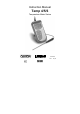
Instruction Manual Temp 4/5/6 Temperature Meter Series 68X243607 Technology Made Easy ... Rev.
Preface This instruction manual serves to explain the use of the Temp 4/5/6 temperature meter. It functions in two ways: first as a step by step guide to help you operate the meter; second, it serves as a handy reference guide. This manual is written to cover as many anticipated applications of the Temp 4/5/6 meter as possible. If there are doubts in the use of this meter, please do not hesitate to contact the nearest Eutech Instruments/ Oakton Instruments Authorised Distributor.
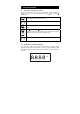
TABLE OF CONTENTS 1. INTRODUCTION 1.1 Introducing the economy series 1 1 2. GETTING STARTED 2.1 2.2 2.3 2.4 2.5 2.6 2.7 Description of Keypad Functions Description of LCD Annunciators Inserting & Removing the Rubber Boot Inserting New Batteries Battery Replacement Connecting the Temperature Sensor Switching the Meter On 2 2 2 3 4 5 5 6 3. CALIBRATION 3.1 Temperature Calibration 3.1.1 3.1.2 Temperature Calibration using Offset Adjustment Temperature Curve Selection (Temp 5 Meter Only) 7 7 7 9 4.
1. INTRODUCTION 1.1 Introducing the economy series Thank you for purchasing the Temp 4/5/6 meter. These microprocessor-based handheld meters are economical and easy to use.
2. GETTING STARTED 2.1 Description of Keypad Functions Temp 4/5/6 meters have six keys on its splash-proof keypad. These keys o o include ON / OFF, CAL, HOLD / ENTER, C/ F, MAX /S (UP) and MIN /T (DOWN) keys. ON OFF CAL HOLD ENTER MAX ON/OFF: Powers meter ON or OFF. Meter directly enters measurement mode when you turn it on CAL: Allows temperature calibration of the meter. HOLD/ENTER: Freezes the measured reading; confirm calibration value.
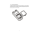
2.3 Inserting & Removing the Rubber Boot 1. To remove meter from rubber boot, push out from the bottom edges of meter until it is completely out of boot. Ensure that the connector of temperature sensor is not connected. 2. To insert meter into rubber boot, slide in from the top of meter before pushing the bottom edges of meter down to set it into position. Lift up the stand at the back of meter for bench top applications if necessary.
2.4 Inserting New Batteries The battery compartment is found at the back of instrument. To open the battery compartment, push in the direction of arrow and lift up the cover. Note the polarity of battery before inserting into position. After replacement, place cover back and press down until it locks tight.
2.5 Battery Replacement A “LO” annunciator in the LCD alerts you when battery power is running low. Replace with the same type as recommended by the manufacturer. LO . °C Caution: Power off the meter when changing battery. 2.6 Connecting the Temperature Sensor To connect a temperature probe into the meter, align the connector of probe to the meter’s socket and push fully until it is in position.
2.7 Switching the Meter On 1. Press ON/OFF key to power up your meter. All the LCD segments display momentarily as the meter performs a self-diagnostic test, per shown in section 2.2. The LCD then switches into measurement mode. 2. The LCD displays “oPEn” if the temperature sensor is faulty, or there is an open circuit. Please refer to section on Troubleshooting if in doubt.
3. CALIBRATION 3.1 Temperature Calibration The temperature sensor included (only for Temp 5) with your meter is factory calibrated. Over time, the temperature calibration may drift and the probe requires recalibration. The Temp 4/5/6 meters allow you to have a 1-point calibration as fine adjustment by changing its offset value. This is useful if you replace the probe and should recalibrate the probe to the meter. 3.1.1 Temperature Calibration using Offset Adjustment 1.
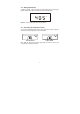
6. Press ENTER key to confirm calibration. 7. The LCD displays “CO” momentarily, and the meter then reverts to measurement mode. See figure below.
3.1.2 Temperature Curve Selection (Temp 5 Meter Only) In the event temperature probe has drifted too far from its original characteristic – due to age and use or if the probe is being replaced, it may be a good idea to match probe to the best curve. There are 3 curves programmed in the unit. To choose the curve, proceed as follows: 1. Connect your temperature probe to the meter.
4. MEASUREMENT 4.1 Taking Measurements 1. Power on the meter. The meter automatically enters Temperature mode. o o The C or F annunciator displays in your LCD to indicate which mode you are taking measurements in. o o 2. Press the C/ F key to toggle between each measurement mode. 4.2 Displaying Maximum and Minimum Readings The EcoScan Temp meter can momentarily display the maximum and minimum temperature measured since you switched the meter on. Simply press MAX/S or MIN/ T key.
4.4 Releasing a Held Reading Press HOLD key again to deactivate HOLD function or to release your frozen reading. The meter returns to measurement mode, and the “HO” annunciator disappears from the LCD. 4.5 Maximum and Minimum Hold Mode With the Maximum and Minimum Hold Mode, the EcoScan Temp meter can be used as a maximum registering (or minimum registering) thermometer. The meter displays the lowest or highest temperature measured since entering the Maximum or Minimum Hold mode. 1. Power on the meter.
5. DISABLE AUTO POWER-OFF FEATURE By default this meter will auto power-off 17 minutes after last key operation. This is to conserve battery power. The auto power-off feature can be disabled in situation where longer periods of monitoring are desired. NOTE: The meter switches back to auto power-off mode as soon as it is turned off. Procedure: 1. With meter off, press down ON/OFF and MIN/▼ keys together. 2. Release ON/OFF key first and wait for 2 seconds before releasing MIN/▼ key.
6. PROBE CARE AND MAINTENANCE For best results, always clean the temperature probe with clean tissue paper after measurement to keep the probe in good working condition. Wash the probe thoroughly with tap water if necessary to wash off any residue. Should there be any thin oil film sticking on the probe, wash with mild detergent or soap and warm water. Rinse probe thoroughly under running water. Blot it dry and clean off with clean tissue.
8. SPECIFICATIONS OF TEMP SERIES Model Temperature Range Resolution Accuracy Temp 4 and 5 (Thermistor) Temp 6 (RTD) -40.0 to 125.0 oC; -40.0 to 257 oF -200.0 to 850.0 ºC; -328.0 to 1562 ºF 0.1 oC/0.1 oF 0.1 ºC/0.1 ºF (for -99.9 to 199.9 ºC /-99.9 to 391.9 ºF); 1 ºC/1 ºF (range< -99.9 ºC/-99.9 ºF & range > 199.9 ºC/391.9 ºF) ± 0.2 oC/0.4 oF ± 0.2 oC/0.
9.
10. WARRANTY & RETURN OF ITEMS This meter is supplied with a warranty against significant deviations in material and workmanship for a period of THREE years from date of purchase whereas probe with a SIX-month warranty. If repair or adjustment is necessary and has not been the result of abuse or misuse within the designated period, please return – freight pre-paid – and correction will be made without charge.
11. RETURN OF ITEMS Authorisation must be obtained from our Customer Service Department or authorised distributor before returning items for any reason. A “Return Goods Authorisation” (RGA) form is available through our authorised distributor. Please include data regarding the reason the items are to be returned. For your protection, items must be carefully packed to prevent damage in shipment and insured against possible damage or loss.
NOTES
For more information on Eutech Instruments/ Oakton Instruments’ products, contact your nearest distributor or visit our website listed below: Oakton Instruments P.O Box 5136, Vernon Hills, IL60061, USA Tel (in U.S.): 888-462-5866 Tel (outside U.S.) 1-847-5497600 Fax: (1) 847-247-2984 E-mail: info@4oakton.com www.4oakton.com Eutech Instruments Pte Ltd. Blk 55, Ayer Rajah Crescent, #04-16/24 Singapore 139949 Tel: (65) 6778 6876 Fax: (65) 6773 0836 E-mail:: marketing@eutechinst.com Web-site: www.eutechinst.