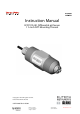
Instruction Manual ECFP21A1A1 Differential pH Sensor 1 ½ Inch NPT Mounting Threads Copyright © 2006 All rights reserved. Eutech Instruments Pte Ltd 68X216866 Rev 0 10/04 Blk 55, Ayer Rajah Crescent, #04-16/24 Singapore 139949 +65 6778 6876 +65 67730836 fax www.thermofisher.
TABLE OF CONTENTS TABLE OF CONTENTS.................................................................................................................................. 2 PREFACE....................................................................................................................................................... 3 SAFETY INFORMATION............................................................................................................................... 4 INTRODUCTION.......................
PREFACE This instruction manual serves to explain the use of the ECFP21A1A1 1½ inch pH sensor and is written to cover as many applications as possible. Please do not hesitate to contact Eutech Instruments or an authorized representative with questions or concerns. The information presented in this instruction manual is subject to change without notice as improvements are made, and does not represent any commitment whatsoever on the part of Eutech Instruments.
SAFETY INFORMATION The ECFP21A1A1 1½ inch pH sensor shall be installed and operated only in the manner specified. Only a skilled, trained or authorized person should carry out installation, setup and operation of the sensor system. Before using the sensor, make sure that the sensor cable is connected as specified. Failure to do so may result in permanent damage to the sensor or controller. Protection against electric shock will be achieved only by observance of the corresponding installation rules.
INTRODUCTION 1.1. General Information Thank you for purchasing the ECFP21A1A1 Differential pH Sensor. This industrial sensor has many enhanced features that offer superior performance in process applications: • Differential pH measurement technology minimizes susceptibility to ground loops. • A built in pre-amplifier eliminates high impedance wiring problems. • A replaceable heavy-duty quad junction salt bridge for extended life in severe applications.
1.3. Safety Instructions The ECFP21A1A1 1½ inch pH sensor should be installed and operated only by personnel familiar with the sensor and qualified for such work. A defective sensor should be returned to Eutech Instruments for repair or replacement. Contact Eutech Instruments to obtain a Return Goods Authorization (RGA) number. No modifications to the ECFP21A1A1 1½ inch pH sensor are allowed. The manufacturer/supplier accepts no responsibility for damage caused by unauthorized modifications.
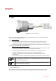
PRODUCT DESCRIPTION 2.1 Sensor Description The ECFP21A1A1 1½ inch pH sensor uses a differential measurement technique to maximize lifetime in continuous industrial applications. The ground rod and encapsulated preamplifier construction reduce the effects of ground loops and allow the pH signals to be transmitted up to 3,000 feet. A replaceable heavy-duty quad junction salt bridge makes it simple to refurbish the sensor when necessary.
2.2 Specifications Wetted Materials……………………………. Sensor Body - CPVC Salt Bridge Junctions - Kynar® pH Electrode - General glass Ground Rod - 316 Stainless Steel O-Ring Seals - Viton® (Consult factory for customized material construction) Operating Temperature…………………….. -5°C to 95°C (23°F to 203°F) Maximum Pressure…………………………. 100 psi @ 100°C (100 psi @ 212°F) Maximum Flow Rate………………………... 3 m/sec (10 ft/sec) Measuring Range…………………………… 0 to 14 pH Resolution……………………………………. 0.
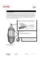
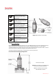
INSTALLATION 3.1 Wiring Figure 3.1: pH Sensor Hook Up There are two different methods for electrical connection between the sensor and the pH controller; either direct or through a junction box. 3.1.1. Direct Connection 1. Use a watertight cord grip to insert the sensor cable into the Alpha pH2000D Controller. Conduit holes are found on the bottom of the Alpha pH2000D controller for this purpose. 2. Connect the sensor wires to the Alpha pH2000D controller as outlined in the controller manual. 3.1.2.
Save the protective cap and use it to keep electrodes moist whenever the sensor is removed from service. When taking a sensor out of storage, soak the sensor in a pH 7 buffer solution for 30 minutes before calibration. If the sensor does not calibrate, refer to Section 4 to review maintenance, refurbishment and troubleshooting options. The sensor should be positioned at least 15° up from horizontal. This will insure that entrained air does not form a pocket around the sensor head. DO NOT USE PIPE SEALANT.
Detailed Pipe Tee Installation Instructions 1. Wiring: a. Route the cable – either through conduit or on a cable tray. b. Insert the sensor cable into the Alpha pH2000D controller through a watertight cord grip. Conduit holes are provided for the cord grip on the bottom of the Alpha pH2000D controller. c. Connect the sensor wires into the Alpha pH2000D sensor terminal block as shown in the Alpha pH2000D manual. 2. Calibrate: a. Power the Alpha pH2000D controller. b.
Detailed Insertion Mount Installation Instructions 1. Wiring: c. Route the sensor cable through the 1.5 inch extension pipe. d. Apply PTFE tape to the sensor threads. e. Attach the sensor to the 1.5 inch NPT coupling by turning the sensor in a clockwise direction until secure. f. Either route the cable directly to the Alpha pH2000D or splice the wires in a junction box and use an extension cable. g. Insert the cable into the Alpha pH2000D controller through a watertight cord grip.
pH SENSOR MAINTENANCE 4.1 Cleaning the pH Sensor Head 4.1.1 In order to maintain an accurate measurement value, the sensor will need occasional maintenance. The maintenance interval will be dictated by the process in which it is installed. The harsher the process, the more often the sensor will require maintenance. Regular maintenance will yield a longer sensor life. 4.1.2 The sensor cleaning procedure is as follows: 4.1.2.
4.2.4 Slowly fill the reservoir with 7pH Standard Cell Filling Solution so the solution just covers the reference O-ring. Do not over fill. Overfilling will lead to excessive pressures that will affect the junction potentials of the reference. 4.2.5 Slowly screw the new salt bridge clockwise onto the sensor head until secure. Tighten the salt bridge with a 15/16 wrench (24mm) until snug. Do not over tighten. Maximum torque: 10 lbs⋅in (1.13 N⋅m) 4.2.
Temperature Span Disconnect the BLACK and YELLOW sensor wires from the analyzer. Use an ohmmeter to measure the resistance between the BLACK and YELLOW wires. The meter should measure a resistance corresponding to the sensor temperature as outlined in the following table. Sensor Temperature 5C 15C 25C 35C 45C Thermistor Resistance 630 Ω 430 Ω 300 Ω 215 Ω 155 Ω If the measured resistance is within 10 to 20 ohms of the expected value, the element should be satisfactory.
• 15X403101 - Protected CPVC Salt Bridge(O-ring included) • ECRE005 – 480 ml pH Sensor Storage Solution 5.2 pH Buffer Standards Description • EC-BU-4BT pH 4 Buffer Standard (480 ml) • EC-BU-7BT pH 7 Buffer Standard (480 ml) • EC-BU-10BT pH 10 Buffer Standard (480 ml) WARRANTY This electrode is supplied with a six-month warranty against significant deviations in material and workmanship.