Instruction Manual CON 6/TDS 6 Hand-held Conductivity/TDS Meter 68X243618 Technology Made Easy ... Rev.
Preface This manual serves to explain the use of the Conductivity and TDS handheld meters. The models covered are the CON 6 and TDS 6. This manual functions in two ways: first as a step by step guide to help you operate the meter; second, it serves as a handy reference guide. This manual is written to cover as many anticipated applications of the Conductivity and TDS handheld meters as possible.
TABLE OF CONTENTS 1 2 INTRODUCTION DISPLAY & KEYPAD FUNCTIONS 2.1 2.
14 ADDENDUM 2: CALCULATING tDS CONVERSION FACTOR 46 15 Addendum 3: calculating temperature coefficients 47 16 WARRANTY 49 17 RETURN OF ITEMS 50
Instruction Manual 1 CON 6/TDS 6 INTRODUCTION Thank you for purchasing CON 6/TDS 6 Conductivity/TDS meter. These economy microprocessor-based handheld meters deliver up to ±0.5% full-scale accuracy. It has a large custom LCD (Liquid Crystal Display) for clear and easy reading. CON 6 measures Conductivity (µS/mS) and Temperature (°C) while the TDS 6 measures Total Dissolved Solids (TDS) and Temperature (°C).
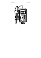
Instruction Manual CON 6/TDS 6 CON 6 mS Conductivity/ ° C Meter ON OFF HOLD ENTER CAL MODE 2
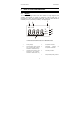
Instruction Manual 2 CON 6/TDS 6 DISPLAY & KEYPAD FUNCTIONS 2.1 Display The meter has a large custom LCD that consists of 4-digit segments and operation annunciators for uS/mS (or ppm/ppt for TDS 6 meter) and °C (Temperature). Other annunciators include “HO” (when the HOLD function is activated) and “LO” (low battery condition). See Figure below. 7 5 6 % HO LO °C m µS pptm 4 3 2 1 LCD and Customized Annunciators for CON 6/TDS 6 meter 1. Primary display 4. Temperature indicator 2.
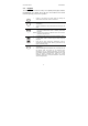
Instruction Manual 2.2 CON 6/TDS 6 Keypad The CON 6 / TDS 6 meter has 6 keys on its splash-proof keypad; ON/OFF, HOLD/ENTER, CAL, MODE, ▲ and ▼ keys. Some buttons have several functions depending on its mode of operation. ON OFF CAL HOLD ENTER • Powers on and shuts off the meter. Takes you directly into measurement mode when meter is switched on. • Enters into calibration mode for Conductivity/TDS and Temperature. • To abort calibration or setup mode without confirming any set value.
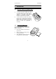
Instruction Manual 3 3.1 CON 6/TDS 6 PREPARATION Inserting & Removing Rubber Boot (Rubber Boot sold separately) 1) To remove meter from rubber boot, push out from the bottom edges of meter until it is completely out of boot. Ensure that the cables of Conductivity electrode or temperature probe are not connected. 2) To insert meter into rubber boot, slide in from the top of meter before pushing the bottom edges of meter down to set it into position.
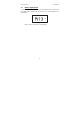
Instruction Manual 3.3 CON 6/TDS 6 Battery Replacement A “LO” annunciator in the LCD alerts you when battery power is running low. See Figure below. Replace with the same type as recommended by the manufacturer. LO µS "LO" Battery Condition Caution: Power off the meter when changing battery.
Instruction Manual 3.4 CON 6/TDS 6 Conductivity Electrode Information The CON 6/TDS 6 hand-held meter is supplied with a conductivity/TDS electrode with a BNC connector. This conductivity/TDS electrode (Order Part Number: ECCONSEN91B/ 35606-55) comes with Stainless Steel rings, cell constant of K = 1.0, and a built-in temperature sensor for Automatic Temperature Compensation (ATC). Its specially designed Ultem-body housing has good chemical resistant properties.
Instruction Manual CON 6/TDS 6 NOTE: 1) DO NOT remove the protective probe guard during measurement and calibration as it may affect your readings. 2) We recommend that you do not submerge the probe above the protective guard. You can submerge the cable for brief periods of time, but not continuously. See Section 7 – “Probe Care and Maintenance” for more information.
Instruction Manual 3.5 CON 6/TDS 6 Connecting the Probe to Meter 1) To connect electrode into meter, align the connector slots with the posts of meter’s socket and rotate connector clockwise until it locks. 2) To remove, simply rotate the connector in anti-clockwise direction until it unlocks, and slide the connector off the socket. 3) Insert the mini phono jack of temperature sensor into the socket on the meter as shown below.
Instruction Manual 3.6 CON 6/TDS 6 Switching the Meter On When switching the meter on, it will go through a series of display, showing the various setup parameters.
Instruction Manual CON 6/TDS 6 Press ON/OFF key to power up your meter. 1) The first screen shows [Con 6] (or [tdS 6]) which is the meter’s name. 2) Second screen shows [C 1.0] which is the conductivity cell constant, k. You can select different cell constant of 0.1, 1.0 or 10.0. Refer to Section on Advance Setup. Default value is k=1.0. 3) Third screen shows [t 25.0 °C] which is the Normalization Temperature. You can set Normalization Temperature at either 25 °C or 20 °C.
Instruction Manual 3.7 CON 6/TDS 6 Change Conductivity/ TDS ÙTemperature Measurement Mode To switch between Conductivity/ TDS measurement mode and Temperature measurement mode, simply press the MODE key. The customized annunciator helps indicate the measurement parameter you are in.
Instruction Manual 4 CON 6/TDS 6 CALIBRATION 4.1 Important Information on Meter Calibration Your meter has five measuring ranges. You can calibrate one point in each of the measuring ranges (up to five points). If you are measuring values in more than one range, make sure to calibrate each of the ranges you are measuring. The following table lists the corresponding conductivity and TDS ranges.
Instruction Manual 4.2 CON 6/TDS 6 Preparing the Meter for Calibration Before starting calibration, make sure you are in the correct measurement mode. For best results, select a standard value close to the sample value you are measuring. Alternatively use a calibration solution value that is approximately 2/3 the full-scale value of the measurement range you plan to use. For example, in the 0 to 2000 µS conductivity range, use a 1413 µS solution for calibration.
Instruction Manual CON 6/TDS 6 NOTE: The factory default value for normalization temperature is 25 °C. If you need to normalize to a value other than 25 °C, see Section 6.6 – Normalization Temperature. 4.3 Selection of Automatic or Manual Calibration This meter is capable of performing either automatic (only CON 6) or manual calibration.
Instruction Manual 4.4 CON 6/TDS 6 Automatic Calibration (Conductivity) In the Automatic Calibration mode, the meter is capable of accepting either single-point or up to 4 points for multi-point calibration with maximum of 1 point per specific measurement range. For the known calibration standard values refer to Table 1 in Section 4.3. Measurement Mode 1) If necessary, press MODE key to select conductivity mode.
Instruction Manual CON 6/TDS 6 IMPORTANT NOTES: 1. Meter allows a tolerance range of ±40% of its calibration standard. An error message “Err 1” will be displayed for 3 seconds if you attempt to calibrate with a solution whose value is outside the tolerance range. For instance: For 1413 µS conductivity calibration standard, 40% tolerance is from 848 µS to 1978 µS. 2.
Instruction Manual 4.5 CON 6/TDS 6 Manual Calibration (Conductivity or TDS) In Manual Calibration mode, you can use customized conductivity calibration standards (specific to your own application) and calibrate the meter. The following example shows calibration sequence to 12.00 mS conductivity calibration standard. Procedure is similar for CON 6 and TDS 6 meters. 1) Measurement Mode If necessary, press MODE key to select conductivity mode.
Instruction Manual 4.6 CON 6/TDS 6 Temperature Calibration The Conductivity electrode (Refer to Accessories section for order number) has a built-in temperature sensor for ATC. The temperature sensor is factory calibrated to the meter. Calibrate your sensor only if you suspect temperature errors that may have occurred over a long period of time or if you have a replacement probe. 1) Make sure that the phono jack (for temperature measurement) is properly connected to the meter. See Figure in Section 3.
Instruction Manual 5 CON 6/TDS 6 MEASUREMENT The CON 6/TDS 6 meter is capable of taking measurements with automatic or manual temperature compensation. 5.1 With Automatic Temperature Compensation (ATC) For ATC, make sure the phono jack of the probe (see Figure in Section 3.5) is securely inserted. The conductivity/TDS reading displayed will be compensated for according to the normalization temperature (20 °C or 25 °C) selected. See Section 6.6 – Normalization Temperature.
Instruction Manual 5.2 CON 6/TDS 6 Without ATC (Manual Temperature Compensation) For manual temperature compensation, simply unplug the probe’s phono jack (not BNC) from the meter. To use manual temperature compensation, you need to enter the temperature value of your process into the meter. This is the value at which the reading will manually temperature compensates. You can select any temperature between 0 and 50 °C (32 to 122 °F). Default value is 25 °C.
Instruction Manual 5.3 CON 6/TDS 6 Taking Measurements To take readings: 1) Rinse the probe with de-ionized or distilled water before use to remove any impurities adhering to the probe body. Shake or air dry. To avoid contamination or dilution of your sample, rinse probe with a small volume of your sample liquid. 2) Press ON to switch on meter. 3) Dip the probe into the sample. 4) Allow time for the reading to stabilize. Note the reading on the display.
Instruction Manual CON 6/TDS 6 Auto-ranging Manual ranging: 0 - 20.00 uS/cm µS mS Manual ranging: 0 - 200.0 mS/cm Manual ranging: 0 - 200.0 uS/cm µS µS mS µS Manual ranging: 0 - 20.00 mS/cm Manual ranging: 0 - 2000 uS/cm NOTE: If the value of the solution you are measuring is higher than the range selected [Or] will appear on the primary display. Press RANGE until the correct range is selected. The meter resets to the Auto-ranging function once it is turned off.
Instruction Manual 5.5 CON 6/TDS 6 HOLD Function This feature lets you freeze the display for a delayed observation. HOLD can be used any time in measurement mode. 1) 2) To hold a measurement, press the HOLD key while in measurement mode. [HO] will appear on the display. µS HOLD ENTER HO To release the held value, press the HOLD again. Continue to take measurements. NOTE: This meter shuts off automatically after 20 minutes of nonuse.
Instruction Manual 6 6.1 CON 6/TDS 6 ADVANCED SETUP FUNCTIONS Advanced Setup Overview The advanced setup mode lets you customize your meter’s preferences and defaults. To enter advanced setup mode: 1) Make sure that the meter is switched-off. 2) Press ON and MODE key simultaneously, holding both keys for 2 seconds. First release ON key first before releasing the MODE key. 3) [StUP] indicator will appear momentarily and [CELC] will appear next.
Instruction Manual CON 6/TDS 6 °C Select Normalization Temperature. Choice of either 20 °C or 25 °C. Default value is 25 °C. Adjust TDS factor from 0.4 to 1.0. Default value is 0.5. (Available in TDS 6 meter only) Select Single Point Calibration. Choice of “Yes” or “No”. Default value is “Yes”. User re-set to factory defaults. Choice of “Yes” or “No”. Default value is “no”.
Instruction Manual CON 6/TDS 6 Meter Off ON OFF MODE Press ON/OFF and MODE keys simultaneously for 2 seconds, release ON/OFF key first then release MODE key a second later. A "StUP" indicator will appear for 1.
Instruction Manual CON 6/TDS 6 Meter Off ON OFF MODE Press ON/OFF and MODE keys simultaneously for 2 seconds, release ON/OFF key first then release MODE key a second later. A "StUP" indicator will appear for 1.
Instruction Manual 6.2 CON 6/TDS 6 Select Cell Constant This meter lets you select a cell constant of K = 1.0, 10, or 0.1. Use a cell of K = 1.0 for midrange measurements Use a cell of K = 10 for high range measurements (above 20 mS or 10 ppt). Use a cell of K = 0.1 for low range measurements (below 20 µS or 10 ppm). The cell included with your meter has a cell constant of K = 1.0. 1) Enter the advanced setup as described in Section 6.1.
Instruction Manual 6.3 CON 6/TDS 6 Automatic Calibration (for CON 6) The automatic calibration allows you to quickly calibrate the meter to any of the four widely used conductivity calibration standards. For a list of calibration standards refer to Table 1 in Section 4.3. In the manual calibration mode, you can use you own customized conductivity calibration standard to calibrate this meter. 1) Enter the advanced setup as described in Section 6.1. 2) Press ▲ or ▼ key until [ACAL] appears on the LCD.
Instruction Manual CON 6/TDS 6 2) Press ▲ or ▼ key until [tdS] appears on the LCD. Press ENTER key. 3) Press ▲ or ▼ key to select a value between 0.4 to 1.0. 4) Press ENTER key to select. The meter will take you back to the menu, [tdS]. 5) Press ▲ or ▼ key to move to the next menu or press CAL to exit to measurement mode. 6.5 Temperature Coefficient The temperature coefficient is the amount of change in conductivity per degree of temperature; it is expressed in percent per °C.
Instruction Manual 6.6 CON 6/TDS 6 Normalization Temperature You can set the meter to normalize its conductivity measurements to a standard temperature of either 25 °C or 20 °C. The default value is 25 °C. 1) 2) Enter the advanced setup as described in Section 6.1. Press ▲ or ▼ key until [t.nr °C] appears on the LCD. Press ENTER key. 3) Press ▲ or ▼ key to select either [25.0 °C] or [20.0 °C]. 4) Press ENTER key to select. The meter will take you back to the menu, [t.nr °C].
Instruction Manual 6.8 CON 6/TDS 6 Restore Factory Default Values This function allows you to reset all parameters to factory default settings. This clears all calibration data and any other setup functions you might have changed. IMPORTANT: Once activated the meter’s settings and calibration data will be erased and always exercise caution as meter reset is not reversible. 1) Enter the advanced setup as described in Section 6.1. 2) Press ▲ or ▼ key until [UrSt] appears on the LCD. Press ENTER key.
Instruction Manual 7 CON 6/TDS 6 PROBE CARE AND MAINTENANCE Keep the conductivity probe clean. Rinse the probe twice, and gently swirl it while you take readings. For best accuracy, soak a dry probe for at least 5 to 10 minutes or longer before calibration. Rinse the probe with deionized or tap water before storing. Never scratch the bands with a hard substance. Do not strike the probe against any hard surface. Do not immerse the probe in oily solutions.
Instruction Manual 8 CON 6/TDS 6 TROUBLE-SHOOTING GUIDE Problem Cause Solution Power on but no display a) Batteries not in place a) Check that batteries are in place and making good contact. b) Batteries not in correct polarity (+ and – position). Unstable readings b) Re-insert batteries with correct polarity. c) Weak batteries c) Replace batteries. a) Air bubbles in probe. a) Tap probe to remove bubbles. b) Dirty probe. b) Clean the probe and re-calibrate.
Instruction Manual 9 CON 6/TDS 6 ERROR MESSAGES LCD Display Indicates Cause Solution “LO” indicator appears. Low battery level. Need new batteries or battery connection is bad. Clean battery contacts. Replace batteries with fresh ones, noting polarity. Err 1 Conductivity calibration error Calibration point is outside the ±40% window in the autocalibration. Check the value of the conductivity calibration solution. Switch to manual calibration mode and calibrate again.
Instruction Manual 10 CON 6/TDS 6 SPECIFICATIONS SPECIFICATIONS DESCRIPTIONS CON 6 Conductivity Range 0 to 20.00, 200.0, 2000 µS/cm; 0 to 20.00, 200.0 mS/cm • Resolution Accuracy TDS Range Resolution Accuracy Temperature Range TDS 6 0.01, 0.1, 1 µS/cm: 0.01, 0.1 ,S/cm ±1% F.S. 0 to 10.00, 10.0 to 100.0, 100 to 1000 ppm; 1.00 to 10.00, 10.00 to 100.0, Up to 200 ppt depending on the TDS factor setting. 0.01, 0.1, 1 ppm; 0.01, 0.1 ppt • • • ±1% F.S. • • -10.0 to 110.0 °C • • 0.1 °C / ± 0.
Instruction Manual CON 6/TDS 6 Auto- & Manualranging • HOLD Function • • • 20 minutes after last key operation • • Inputs BNC for conductivity and phono jack for temperature • • Display Single Custom LCD • • 4 ‘AAA’ Batteries • • > 100 hours • • Meter: 14 x 7 x 3.
Instruction Manual 11 CON 6/TDS 6 ACCESSORIES Replacement Meter and Meter accessories Item Eutech Instruments Oakton Instruments Ordering Code No. Ordering Code No. CON 6 portable conductivity meter complete with conductivity probe of k=1.0 (EC-CONSEN91B/ 35606-55). EC-CON603k 35606-10 CON 6 portable TDS meter complete with conductivity probe of k=1.0 (EC-CONSEN91B/ 35606-55). EC-TDS603K 35606-15 3 ring SS, Ultem body Electrode with ATC & BNC plug (for CON 6), cell constant = 1.
Instruction Manual CON 6/TDS 6 Calibration Solutions 1,413 µS KCl Calibration Solution in 480-ml leak-proof bottle (1 pint) EC-CON-1413BT 00653-18 12.
Instruction Manual 12 CON 6/TDS 6 CONDUCTIVITY THEORY Conductance is a quantity associated with the ability of primarily aqueous solutions to carry an electrical current, I, between two metallic electrodes when a voltage E is connected to them. Though water itself is a rather poor conductor of electricity, the presence of ions in the water increases its conductance considerably, the current being carried by the migration of the dissolved ions.
Instruction Manual CON 6/TDS 6 areas and separation distances, it is possible to standardize or specify conductance measurements. Thus derives the term specific conductance or conductivity. The relationship between conductance and specific conductivity is: Specific Conductivity, S.C.
Instruction Manual CON 6/TDS 6 Some users prefer the use of resistivity units to describe their water, particularly where high purity water is involved. The unit most often used to describe resistivity is megohm-cm, which are simply the reciprocal of conductivity (µS/cm). The chart below shows the relationship between these units. Conductivity, µS/cm Resistivity, megohm-cm 0.056 18 0.1 10 1.0 1.0 2.5 0.4 10.0 0.
Instruction Manual CON 6/TDS 6 Conductivity and Temperature Conductivity in aqueous solutions reflects the concentration, mobility, and charge of the ions in solution. The conductivity of a solution will increase with increasing temperature, as many phenomena influencing conductivity such as solution viscosity are affected by temperature. The relationship between conductivity and temperature is predictable and usually expressed as relative % change per degree centigrade.
Instruction Manual 13 CON 6/TDS 6 ADDENDUM 1: CALIBRATION TIPS You only need one calibration for measurement throughout the entire range of the meter. If a range was not calibrated, the meter automatically detects the closest range calibrated and uses that calibration information. However, only the ranges that were calibrated have maximum accuracy.
Instruction Manual 14 CON 6/TDS 6 ADDENDUM 2: CALCULATING TDS CONVERSION FACTOR You can calibrate your meter using TDS calibration standard solutions. The calibration standard only needs to give the TDS value at a standard temperature such as 25 °C.
Instruction Manual 15 ADDENDUM 3: COEFFICIENTS CON 6/TDS 6 CALCULATING TEMPERATURE To determine the temperature coefficient of your sample solution use this formula: Where: tc = Temperature coefficient 25 = 25 °C CT1 = Conductivity at Temp 1 CT2 = Conductivity at Temp 2 T1 = Temp 1 T2 = Temp 2 NOTE: A controlled temperature water bath is ideal for this procedure. 1. 2. 3.
Instruction Manual 4. 5. CON 6/TDS 6 Calculate the temperature coefficient of your solution according to the formula shown above. Enter the temperature coefficient you calculated into the meter. Refer to Section 6.5 – Temperature Coefficient. The calculated temperature coefficient will not be applied to all the meter readings.
Instruction Manual 16 CON 6/TDS 6 WARRANTY This meter is supplied with a warranty against significant deviations in material and workmanship for a period of THREE years from date of purchase whereas probe with a SIX-month warranty. If repair or adjustment is necessary and has not been the result of abuse or misuse within the designated period, please return – freight pre-paid – and correction will be made without charge.
Instruction Manual 17 CON 6/TDS 6 RETURN OF ITEMS Authorization must be obtained from our Customer Service Department or authorized distributor before returning items for any reason. A “Return Goods Authorization” (RGA) form is available through our authorized distributor. Please include data regarding the reason the items are to be returned. For your protection, items must be carefully packed to prevent damage in shipment and insured against possible damage or loss.
Instruction Manual CON 6/TDS 6 NOTES 51
Instruction Manual CON 6/TDS 6 For more information on Eutech Instruments/ Oakton Instruments’ products, contact your nearest distributor or visit our website listed below: Oakton Instruments P.O Box 5136, Vernon Hills, IL60061, USA Fax: (1) 847-247-2984 www.4oakton.com www.oaktoninstruments.com Eutech Instruments Pte Ltd. Blk 55, Ayer Rajah Crescent, #04-16/24 Singapore 139949 Tel: (65) 6778 6876 Fax: (65) 6773 0836 E-mail: marketing@eutechinst.com Web-site: www.eutechinst.