
User Guide


Instruction Manual pH 510/ Ion 510
4
2 STARTING UP
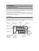
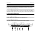
Connect the accessory connectors at the rear of the instrument panel. During operation, it is important that
water does not get onto the BNC connector. Also avoid touching the connector with soiled or wet hands.
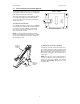
2.1 Connecting the Sensor Electrode
Slide the electrode connector of the electrode over the socket of the meter’s BNC connector marked ‘INPUT’.
The meter can accept any standard pH, ORP, or Ion Selective Electrode with a BNC connector. Align the slot
of the electrode connector with the posts of the socket. Rotate the connector clockwise until it locks. For
separate reference electrodes, push the electrode pin into jack marked ‘REF’.
2.2 Connecting the Temperature Probe
Insert the temperature probe (provided) into the connector marked ‘ATC’.
2.3 Connecting the A/C Adapter
Slide in the adapter jack of the A/C adapter into the back panel marked ‘DC’ until it is firmly seated. Ensure that
the power is switched off before installation and the correct voltage adapter is used.
2.4 Connecting the Chart Recorder
You can connect chart recorders or external output devices for continuous printout. Plug in the input connector
and ground pin of the chart recorder into the ports marked ‘REC’ and ‘GND’ respectively.
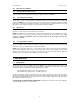
Temp. probe
Sensor electrode
Separate ref. electrode
Chart recorder
Ground
AC/DC Adapter