Instruction Manual pH/Ion 510 Bench pH/Ion/mV Meter 68X090811 Rev. 6 08/04 Technology Made Easy ...
PREFACE Thank you for choosing the pH 510 pH/mV/Temperature or Ion 510 Ion/pH/mV/Temperature bench meter. The instruction manual functions in two ways: firstly as a step-by-step guide to help you operate the 510 series meter. Secondly, it serves as a handy reference guide. The instruction manual is written to cover as many anticipated applications of the pH/Ion 510 Bench meter series as possible. If there are doubts in the use of the instrument, do not hesitate to contact the nearest Authorized Distributor.
TABLE OF CONTENTS 1 INTRODUCTION ........................................................................................................................... 1 1.1 1.2 1.3 1.4 2 STARTING UP .............................................................................................................................. 4 2.1 2.2 2.3 2.4 2.5 2.6 3 Storage ......................................................................................................................................................
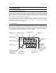
Instruction Manual pH 510/ Ion 510 1 INTRODUCTION 1.1 Introducing the 510 Bench Series The pH 510 and Ion 510 bench meters are microprocessor-based which incorporates new ASIC (Application Specific Integrated Circuit). It is designed with convenience in mind, and offers many advanced user-friendly features. The meters are capable of storing and recalling up to 50 data sets in its non-volatile memory.
Instruction Manual 1.3 pH 510/ Ion 510 Keypad A large splash proof membrane keypad with tactile feedback makes meter easy to use. Names and symbols describe the function button controls. Key Measurement Mode Calibration / Setup Mode ON/OFF Powers the meter ON/OFF. When the meter is switched on, it automatically starts in the last mode of operation. ~ CAL/MEAS Toggles between the measurement and calibration modes of the meter. In SETUP mode, pressing CAL/MEAS key returns to the measurement mode.
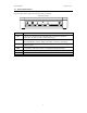
Instruction Manual 1.4 pH 510/ Ion 510 Rear Instrument Panel This 510 series meter provides a complete set of connectors for the various accessories commonly used. Listed in the table are the details of the connections that you can make. Rear View of Meter Connection ATC Function For phono jack connection from the temperature probe for Automatic Temperature compensation. The probe should be a 30KΩ thermistor type. INPUT For connection to sensor electrodes with BNC type connectors.
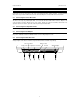
Instruction Manual pH 510/ Ion 510 2 STARTING UP Connect the accessory connectors at the rear of the instrument panel. During operation, it is important that water does not get onto the BNC connector. Also avoid touching the connector with soiled or wet hands. 2.1 Connecting the Sensor Electrode Slide the electrode connector of the electrode over the socket of the meter’s BNC connector marked ‘INPUT’. The meter can accept any standard pH, ORP, or Ion Selective Electrode with a BNC connector.
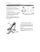
Instruction Manual 2.5 pH 510/ Ion 510 Connecting the Electrode Holder (Optional) Bottom of Meter The integral electrode holder serves as a handy holder for mounting a few pH/Ion electrodes or a temperature probe during measurement or when idle. This meter’s base plate has a side metal bar to which you can attach an integral swivel electrode holder. You can mount the electrode holder on either right or left side of the meter.
Instruction Manual 2.6 2.6.1 pH 510/ Ion 510 Steps Prior to Calibration Switching ‘ON’ and ‘OFF’ the meter Press ON key to switch meter on. All the LCD segments will display momentarily for a few seconds and the LCD then switches to the last measurement mode. To switch meter off, press OFF key. 2.6.2 Selecting Measurement Mode The measurement modes available for the pH 510 meter are pH, mV (for ORP) and Temperature, while the Ion 510 meter has Ion, pH, mV and Temperature measurement modes.
Instruction Manual pH 510/ Ion 510 All new calibrations will override existing stored calibration data at these calibration points. It is recommended that you perform at least a 2-point calibration using buffers that bracket (one above and one below) the expected sample range, starting with pH 7 buffer first. You can perform a 1-point calibration, but make sure that the buffer value is close to the sample value you are measuring.
Instruction Manual pH 510/ Ion 510 CAL 7. pH Wait for the measured pH value to stabilize (when the [READY] indicator displays in the left-hand corner). NOTE ERR 7.00 pH If the upper measured display is not within the buffer acceptable window (refer to Hint below) an error message and the electrode icon flash upon pressing the ENTER key. Refer to Section 7, Troubleshooting Guide. Check electrode condition and recalibrate. Press CAL/MEAS key to exit calibration and resume to the measurement mode.
Instruction Manual 3.2 pH 510/ Ion 510 Ion Concentration Calibration (For Ion 510 only) The Ion 510 meter is capable of up to 3-point ion calibration (minimum 2 points) with choice of 4 options to ensure accuracy across the entire measurement range. Note that the ion measurement mode accepts input of only ± 500 mV. Ion calibration options include 0.10, 1.0, 10.0 or 100.0 ppm. All calibration should be at least one decade apart from each other. For example you may perform 3 point calibration to 0.10, 1.
Instruction Manual pH 510/ Ion 510 If you are performing a 3-point calibration, rinse off the electrode with deionized water, place it in the next calibration standard and proceed as follows. 8. Allow meter to stabilize in the next calibration standard. Once the reading has stabilized, press the ENTER key to confirm the third calibration point.
Instruction Manual 3.3 pH 510/ Ion 510 mV Calibration 1. Make sure the meter is on and if necessary, press the MODE key to select mV mode. The [mV] indicator appears in the upper right-hand corner of the display. 2. Press the CAL/MEAS key. The [CAL] indicator appears above the upper display that displays the relative mV reading. The lower display shows the absolute mV value.
Instruction Manual 3.4 pH 510/ Ion 510 Temperature Calibration In this calibration procedure, the ATC probe is attached to the meter and the [ATC] annunciator is displayed on the right hand side of the LCD. 1. Dip the temperature probe into a solution of known temperature, such as a temperature bath for a few minutes until the temperature probe stabilizes. 2. To perform temperature calibration, you must be in the pH measurement mode. 3.
Instruction Manual pH 510/ Ion 510 4 MEASUREMENT 4.1 Automatic Temperature Compensation (ATC) For ATC measurements, simply attach the temperature probe into the meter (see Section 2.2). The [ATC] annunciator lights up on the LCD. NOTE If you are using a temperature probe, the probe must be submersed in the liquid you are measuring so that the sample temperature can be 4.2 Manual Temperature Compensation (MTC) Important: For MTC, you must disconnect the temperature probe. 1. Switch the meter on.
Instruction Manual 4.3 pH 510/ Ion 510 Taking Measurements Be sure to remove any electrode soaker bottle or protective rubber cap from the electrode before measurement. To take readings: 1. Rinse the electrode with distilled or tap water before use to remove any impurities adhering to the electrode body. If the pH electrode had dehydrated, soak it for 30 minutes in EC-RE005/ 00653-04 electrode storage solution. (See Electrode Care - Section 6) 2. Press ON key to switch on meter.
Instruction Manual 4.4 pH 510/ Ion 510 HOLD Function This feature lets you freeze the value of the measured reading. HOLD can be used anytime when in [MEAS] mode. You can store the held reading into memory by pressing MI key. HOLDing a measurement To hold a measurement, press the HOLD key while in measurement mode. [HOLD] annunciator will appear on the display. Releasing a Held Value To release the held value, press HOLD key again. [HOLD] annunciator will disappear from the LCD.
Instruction Manual pH 510/ Ion 510 Memory Recall 1. In the measurement mode, press MR key once to retrieve the last reading stored. The memory location screen – “MEM”, “LOC” and the memory number – will flash on the display. 2. Press the ENTER key to recall the reading stored under that memory number. 3. If necessary, you can selectively choose to view any data that is stored by using ¿ or À key. For example to view the third data location set to LOC 3 from last stored location of LOC 5.
Instruction Manual pH 510/ Ion 510 5 SETUP FUNCTIONS The advanced SETUP mode lets you customize your meter’s preferences and defaults: P1.0: Memory Clear (Clr) P2.0: Viewing electrode data (ELE) P3.0: Selecting buffer sets (bUF) P4.0: Reset to factory default settings (rSt) To enter the SETUP mode: 1. Turn meter OFF. 2. With meter off, press and hold the MODE key, and press and release the ON key. The display will show the [SETUP] indicator.
Instruction Manual 5.2 pH 510/ Ion 510 P2.0 Viewing Electrode Diagnosis This program lets you check the electrode parameters for diagnostic purposes. Depending on the last display mode, displayed electrode information varies. Only these readings can be viewed: Last Display Mode pH Ion mV Electrode Property Offset Slope in mV % in mV in mV - 1. Enter the SETUP mode as described above. The meter automatically goes to program 1.0. 2.
Instruction Manual 5.3 pH 510/ Ion 510 P3.0 Selecting pH Buffer Standard This program lets you select between two standard calibration buffer sets, depending upon your requirements. The available standards are USA and NIST. 1. Enter the SETUP mode as described in this section earlier. The meter automatically goes to program P1.0. 2. Press ¿ or À key to scroll through the programs until you view “bUF” in the upper display and P3.0 in the lower display. The buffer annunciator also appears. 3.
Instruction Manual pH 510/ Ion 510 6 pH ELECTRODE MAINTENANCE pH electrodes are susceptible to dirt and contamination and need to be cleaned regularly depending on the extent and condition of use. Refer to Section 6.3 for more details on cleaning pH electrode. 6.1 Storage For best result, always keep the pH electrode bulb wet, preferably with the use of storage solution. pH 4 buffer is also acceptable as a storage medium. Do not store in deionized water.
Instruction Manual 6.3 pH 510/ Ion 510 Electrode Cleaning pH electrodes that are mechanically intact and not in use for a short period of time can be restored to normal performance by one or a combination of following procedures: a) Salt deposits Dissolve the salt deposits by immersing the electrode in a container filled with some tap water for ten to fifteen minutes. Then thoroughly rinse with de-ionized water. b) Oil / Grease Films Wash the pH electrode bulb in mild detergent and water.
Instruction Manual 6.4 pH 510/ Ion 510 pH Electrode Rejuvenation CAUTION: Proper protective eyewear and precautionary measures must be used when performing the rejuvenation procedure as it involves the use of concentrated acid and alkaline. Generally, if procedure of storage and maintenance had been closely followed, the pH electrode can be used immediately. However, should the electrode response become sluggish, it may be possible that the glass bulb has dehydrated.
Instruction Manual pH 510/ Ion 510 7 TROUBLESHOOTING GUIDE 7.1 Error Messages The table provides a quick guideline for diagnosis of possible problems indicated by the messages generated by the 510 meter series. The table also provides possible solutions to problems encountered. Diagrams inserted below. Display Screen ERROR INDICATES CAUSE MESSAGE CORRECTIVE ACTION Err.
Instruction Manual 7.2 pH 510/ Ion 510 Troubleshooting PROBLEM PROBABLE CAUSE REMEDIAL ACTION No display a) Mains power not switched on. a) Switch on the power supply. b) AC Adapter socket not inserted properly. b) Re-insert AC Adapter socket. Unstable reading a) Insufficient reference electrolyte in electrode. a) Fill electrode with reference electrolyte. b) Broken electrode b) Replace electrode. c) External ‘noises’ or induction ( e.g.
Instruction Manual pH 510/ Ion 510 8 ADDITIONAL INFORMATION 8.1 pH and Temperature Automatic Temperature Compensation (ATC) compensates for temperature changes. Some solutions show an increase while others a decrease in pH with the same temperature change. Record the solution temperature along with the pH value, or the measurement may be meaningless. Temperature changes also affect the signal the pH electrode sends to the meter and causes a loss of accuracy for the reading.
Instruction Manual 8.4 8.4.1 pH 510/ Ion 510 List of Accessories Replacement Meter and Accessories Item Description Eutech Instruments Oakton Instruments Order Code No. Order Code No.
Instruction Manual 8.4.4 pH 510/ Ion 510 Ion Selective Electrodes (ISE) Ask our distributors for more details regarding ISE and its standard solutions. The table below lists the range of electrodes available. All ISE are supplied with 1m cable length and BNC connector.
Instruction Manual 8.5 pH 510/ Ion 510 Specifications pH 510 Ion 510 pH Range Description 0.00 to 14.00 pH 9 9 Resolution 0.01 pH 9 9 ± 0.01 pH + 1 count 9 9 Accuracy Ion Concentration Range 9 0.01 to 1999 ppm (± 500 mV input) Resolution Accuracy 0.01 pm (0.01 to 0.99 ppm); 0.1 ppm (1.0 to 199.9 ppm); 1 ppm (200 to 1999 ppm) 9 ±0.5% Full Scale for mono-valent ions ±1.0 % Full Scale for di-valent ions 9 9 9 mV Range Yes Resolution 0.1 mV (± 199.
Instruction Manual pH 510/ Ion 510 9 WARRANTY This bench meter is supplied with a 3-year warranty from manufacturing defects and electrodes for 6 months from the date of purchase. If repair or adjustment is necessary and has not been the result of abuse or misuse within the designated period, please return – freight pre-paid – and correction will be made without charge. Eutech Instruments/ Oakton Instruments will determine if the product problem is due to deviations or customer misuse.
For more information on Eutech Instruments/ Oakton Instruments’ products, contact your nearest distributor or visit our website listed below: Oakton Instruments P.O Box 5136, Vernon Hills, IL60061, USA Fax: (1) 847-247-2984 www.4oakton.com www.oaktoninstruments.com Eutech Instruments Pte Ltd Blk 55, Ayer Rajah Crescent, #04-16/24 Singapore 139949 Tel: (65) 6778 6876 Fax: (65) 6773 0836 E-mail: marketing@eutechinst.com Web-site: www.eutechinst.