
Instruction manual

Instruction Manual PC 510
5
4 PREPARATION
4.1 Connecting the Sensor Electrode
4.1.1 To connect the pH electrode:
1. Slide the BNC connector of the probe over the BNC connector socket on the meter. Make sure the
slots of the connector are in line with the posts of the socket. Rotate and push the connector
clockwise until it locks.
2. To remove electrode, push and rotate the connector anti-clockwise. While holding onto the metal
part of connector, pull it away from the meter
NOTE:
Keep connector dry and clean. Do not touch connector with soiled hands.
CAUTION
: Do not pull the probe cord or the probe wires might disconnect.
4.1.2 To connect the conductivity/temperature probe:
1. Line up the notch and 6-pins on the probe connector with the holes in the connector located on the
top of the meter. Push down and screw the metal sleeve to lock the probe connector into place.
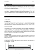
See Figure 1 on page 1 for the meter rear panel view.
2. To remove probe, unscrew the metal sleeve and slide up the probe connector. While holding onto
the metal sleeve, pull probe away from the meter.
NOTE
: Follow the same directions to connect an optional separate temperature element.
Keep connector dry and clean. Do not touch connector with soiled hands.
CAUTION
: Do not pull on the probe cord or the probe wires might disconnect.
4.2 Connecting the A.C. Adapter
1. Before plugging in the A.C. adapter, switch off the meter and the power source of the A.C.
adapter. This is a safety precaution that should be adhered to safeguard your meter.
2. The A.C. adapter should have the following settings:
Output voltage: 9 V D.C.
Current: 500 mA
NOTE
: Ensure that the input mains voltage (110/220/240 V) matches your adapter requirements.
3. Insert the D.C. jack into the socket at rear panel of the meter as shown in Figure 1on page 1.
4. Switch on the power to the adapter, followed by the meter.