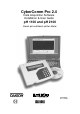
CyberComm Pro 2.4 Data Acquisition Software Installation & User Guide pH 1100 and pH 2100 Bench pH and Bench pH/Ion Meter Technology Made Easy ...
PREFACE Thank you for selecting the pH 1100/ pH 2100 benchtop meter. This meter comes with the CyberComm Pro DAS Software which allows you easy access and communication via a computer with connection to the meter. The instruction manual serves to explain the use of the CyberComm Pro step-by-step installation and user guide to help you familiarize with the software’s features and functions.
TABLE OF CONTENTS 1 DATA ACQUISITION IN WINDOWS VERSION 1.1 The CyberComm DAS Package 1.2 System Requirements 1.2.1 Setting the Communication Parameters 2 INSTALLATION OF CYBERCOMM DATA ACQUISITION SOFTWARE (DAS) 2.1 2.2 2.3 Loading of CD-ROM User Name and Organisation Entry Splash Screen 3 CYBERCOMM PRO MAIN MENU 3.1 3.2 3.3 Communication Settings (File) Data Log Options (File) Connect to Meter (File) 4 MAIN WINDOW (AFTER CONNECTING METER TO COMPUTER) 4.1 4.1.1 4.1.2 4.2 4.3 4.3.1 4.3.2 4.3.3 4.3.4 4.
Instruction Manual 1 CyberComm pH 1100/ 2100 DATA ACQUISITION IN WINDOWS VERSION 1.1 The CyberComm DAS Package The CyberComm Data Acquisition Software (DAS) package is a user-friendly data acquisition package that provides a convenient way to capture data for future analysis. This CyberComm Pro is only able to run on Windows© Operating System (refer to 1.2 System Requirements for details).
Instruction Manual 2 2.1 CyberComm pH 1100/ 2100 INSTALLATION OF CYBERCOMM DATA ACQUISITION SOFTWARE (DAS) Loading of CD-ROM See Figure 1. Before running the program, check that the pH 1100/ pH 2100 meter is properly connected to the computer. It is preferable to connect to either one of the COM (serial) ports available on a computer. Note the number of the COM port that you have connected to the meter as this will be required in setting up the CyberComm DAS later. a) Turn on the computer (PC).
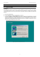
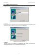
Instruction Manual 2.2 CyberComm pH 1100/ 2100 User Name and Organisation Entry The CyberComm program (as below) prompts you to enter the name of the user and organization. Figure 2: CyberComm Pro Installation/ User Information See Figure 2. Follow the instruction in the subsequent menu for your desired location of this file to be saved. Make relevant changes until the setup is completed (shown below). Click on the Finish button. Figure 3: CyberComm Pro Installation/ Setup Complete See Figure 3.
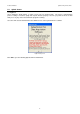
Instruction Manual 2.3 CyberComm pH 1100/ 2100 Splash Screen See Figure 4. Upon clicking the Finish button, a splash screen pops up (shown below). The meter’s communication protocol setting i.e. baud rate, parity and stop bits must be properly set before you power the meter on. DO NOT press any key on the meter while the program is running. Go to the URL stated to download the latest FREE version of the CyberComm Pro software.
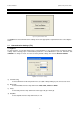
Instruction Manual 3 CyberComm pH 1100/ 2100 CYBERCOMM PRO MAIN MENU Figure 5: CyberComm Main Menu See Figure 5. Select Communications Settings and set the appropriate requirements before connecting the meter. 3.1 Communication Settings (File) See Figure 6. To make changes, use the drop-down menu of each parameter to set to desired values to match the meter’s settings. After selecting proper communication parameters, select OK button to proceed. Otherwise click CANCEL if no change is made.
Instruction Manual 3.2 CyberComm pH 1100/ 2100 Data Log Options (File) See Figure 7. a) Time between successive readings (1-3600 sec). Default is 10 sec. Select the time lag preferred between each successful reading using the arrow keys. b) Length of Time to Capture Data. Default is 0 min. (0= indefinitely, units = min) Select the total length of time preferred to capture data using the arrow keys. The data capture will automatically stop upon reaching the set amount of time.
Instruction Manual 4 4.1 CyberComm pH 1100/ 2100 MAIN WINDOW (AFTER CONNECTING METER TO COMPUTER) CyberComm Pro Manuals (Help) See Figure 8 and 9. The main menu appears with the File and Help drop down menus, each having a list function settings shown below. Soft copies of the CyberComm Pro Software User Guide Manuals are available in the program itself. Select the manual option with reference to the meter you are using.
Instruction Manual CyberComm pH 1100/ 2100 4.1.1 File Options (File) See Figure 10. Select File Options from the File drop down menu. Enter the relevant information for useful future references and type a file name/or file location that you wish to store these details. Click OK upon completion to save information. Figure 10: File Options 4.1.2 About CyberComm Pro (Help) See Figure 6. By selecting About CyberComm Pro from the Help drop down menu, the dialogue box will be shown as below.
Instruction Manual 4.2 CyberComm pH 1100/ 2100 Sub menus & Function Icons on the CyberComm Program See Figure 12. The figure shows the CyberComm Pro software Main Menu after linking with the meter. From this menu, most of the meter key functions can be emulated except calibration of pH probe and CAL EDIT key function.
Instruction Manual 4.3 CyberComm pH 1100/ 2100 Function Icons See Figure 13. See also Figure 12. The function icons on the main menu each serve a vital role in the CyberComm Pro software, providing user friendly one click access. Figure 13: Function Icon Panel (extracted from Figure 11) Icon no. Function Name Description 1 Record Click on this icon to start recording meter readings, readings will be shown on the CyberComm Pro main menu. Data captured will also be stored to the hard disk.
Instruction Manual CyberComm pH 1100/ 2100 Figure 14: Record overwrite prompt Figure 15- Print screen 11
Instruction Manual CyberComm pH 1100/ 2100 Stability definitions High stability: reading is stabilized quickly, but reading is less accurate. Medium stability: reading stability is averaged between high and low stability. Low stability: reading is stabilized slowly, but guarantees high accuracy Icon 11. pH Settings See Figure 16. a) pH Resolution Select the accuracy of your readings by selecting either 0.001 pH resolution or 0.01 pH resolution. b) Temperature Scale Select °C or °F.
Instruction Manual CyberComm pH 1100/ 2100 Icon 12. mV Settings See Figure 17. a) mV Alarm Settings Using the Low and High options, select the ‘safe’ range of readings. Any readings not within the selected range will trigger the alarm alert. b) mV Calibration Due Check to enable the calibration due warning or uncheck to disable it. Calibration due period can be set from 1 to 365 days to remind you of the calibration due.
Instruction Manual CyberComm pH 1100/ 2100 Icon 13. Ion Settings (Only applicable for pH 2100) See Figure 18. a) Ion Settings Select Ion Mode from the drop down menu; Ppm, ppt, mg/l, g/l, mmol/l or mol/l b) Ion Resolution Select High or Low ion resolution mode. Select High when electrode output is ±500 mV value, Low when electrode output is ±1850 mV value. c) Ion Alarm Limit Using the Low and High options, select the ‘safe’ range of readings.
Instruction Manual CyberComm pH 1100/ 2100 Icon 14. Meter Settings See Figure 19. Program your meter functions via this icon on CyberComm Program. a) Date and Time Click on the textbox then a calendar will appear for you to set the date. b) Backlighting Enable or disable the backlight and choose the On period from 0 to 10 minutes. c) Data Log Select Manual for self recording of the readings at different times or choose to have Auto Data logging at the preferred interval timing.
Instruction Manual CyberComm pH 1100/ 2100 4.3.5 Temperature Reading This curve shows the temperature in which the measurement is carried out simultaneously. You can choose to view the reading with or without the temperature curve by clicking on the ‘Show/Hide Temperature’ icon on the icon panel. 4.3.6 Mode Drop down Menu Change Mode of Measurement by selecting the preferred parameter from this drop down menu. 4.3.
Instruction Manual 5 CyberComm pH 1100/ 2100 RETRIEVE RECORDED DATA You are able to view the Recorded Data Readings in a Microsoft Excel© spreadsheet or on your Notepad©/ WordPad© etc. Steps to record and retrieve data in a measurement 1. Follow the steps in Section 3.2: Data Log Options (File) and enter the required information before a measurement you want to keep record of. Key in the desired time interval and measurement duration. 2.
Instruction Manual CyberComm pH 1100/ 2100 Figure 2: Recorded Data in every 10 seconds displayed in Microsoft Notepad© 18
Instruction Manual 6 CyberComm pH 1100/ 2100 EXPORT DATA READINGS You are able to view the Data Readings in a Microsoft Word© document, Microsoft Excel© spreadsheet or on your Notepad©, WordPad© etc. 6.1 Steps to export data readings from CyberComm Professional: While in measurement mode on the CyberComm Professional:1. Click the ‘Recall Memory’ button to view the recorded data readings 2. Select the ‘copy’ icon and the data readings will be copied to the ‘clipboard’ 3.
Instruction Manual 6.3 CyberComm pH 1100/ 2100 Paste data in Microsoft Excel© , WordPad and Notepad Follow steps instructed in Section 6.1: Steps to export data readings from CyberComm Professional: and paste the data copied from the CyberComm Pro to a new document.
Instruction Manual CyberComm pH 1100/ 2100 Figure 5: Paste data readings in a Microsoft Notepad© document 21
Instruction Manual 7 7.1 CyberComm pH 1100/ 2100 PRINT READINGS Printing using a serial printer Connect the pH 1100/ 2100 meter to the serial printer via RS232C cable (refer to the list of accessories). The configuration of the RS232C port is as shown below. 7.
NOTES:
For more information on Eutech Instruments/ Oakton Instruments products, contact your nearest distributor or visit our website listed below: Eutech Instruments Pte Ltd. Oakton Instruments Blk 55, Ayer Rajah Crescent, #04-16/24 Singapore 139949 Tel: (65) 6778 6876 Fax: (65) 6773 0836 E-mail: marketing@eutechinst.com Web-site: http://www.eutechinst.com P.O Box 5136, Vernon Hills, IL60061, USA Tel: (1) 888-462-5866 Fax: (1) 847-247-2984 E-mail: info@4oakton.com Web-sites: www.4oakton.com www.