Instruction Manual CyberScan CON 1500 Bench Conductivity/ TDS/ Resistivity Meter Technology Made Easy ...
PREFACE Thank you for selecting the Eutech Instruments CyberScan CON 1500 bench meter. The instruction manual serves to explain the use of the CyberScan CON 1500 bench meter as a step-by-step operational guide to help you familiarise with the meter’s features and functions. It is structured sequentially with illustration of diagrams that explains the various functions and setup menus available.
TABLE OF CONTENTS 1. INTRODUCTION 1 2. GETTING STARTED 2 2.1. Connectors 3. USING THE METER 3.1. 3.2. 3.3. Conductivity Probes Display/ Keys Screen Display 4. CONDUCTIVITY OPERATION 4.1. 4.2. 4.2.1 4.2.2 4.2.3 4.2.4 4.2.5 4.2.6 4.2.7 4.2.8 4.2.9 4.2.10 4.2.11 4.2.12 4.2.13 4.2.14 4.2.15 4.2.16 Using Setup Overview of Setup Pages in CyberScan CON 1500 Setup Page 1.0: View the Cal data Setup Page 2.0: Set cell constant Setup Page 3.0: Set Temperature Coefficient Setup Page 4.
Instruction Manual CyberScan CON 1500 1. INTRODUCTION Thank you for selecting the Eutech Instruments CyberScan CON 1500 bench-top meter. This instruction manual describes the operation of the meter. The state-of-art meter that you have purchased is easy to operate and will guide you through the various functions by displaying easy to understand prompts.
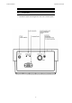
Instruction Manual CyberScan CON 1500 2. 2.1. GETTING STARTED Connectors 1. Review the layout and arrangement of the rear connector panel.
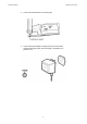
Instruction Manual CyberScan CON 1500 2. Connect the electrode arm to the base plate. 3. Connect the power adapter’s output power jack to the meter’s rear panel DC input power socket and plug in the adapter to a power source.
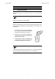
Instruction Manual CyberScan CON 1500 3. USING THE METER 3.1. Conductivity Probes This meter allows you to use either the 2-cell or 4-cell conductivity probes. ) DO NOT connect both probes together. Remove the protective cover from the end of the probe. Prior to use, soak the probe in distilled or deionised water for 10 minutes. You may either:1. Connect the 2-cell probe by plugging its pin connectors into the dual pin sockets located at the rear panel of the meter. 2.
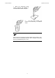
Instruction Manual CyberScan CON 1500 1. Rinse the conductivity probe sensing elements with distilled or deionised water between samples. 2. For long term storage, the probes can be stored dry or in distilled water. ) Note that the cell constant may change slightly due to storage or use, and it must be re-evaluated with the use of standard conductivity solution (standardisation) prior to use.
Instruction Manual CyberScan CON 1500 3.2. Display/ Keys Overview of the meter screen display and function key layout. Press std key to initiate standardisation. Or press std key at the ‘Standardize’ mode allows you to exit and return to measurement mode without accepting the calibration. Press mode to select uS, kohm or TDS. Press setup key to access setup for configuration of meter setting.
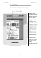
Instruction Manual CyberScan CON 1500 3.3. Screen Display Familiarise yourself with the layout of the digital screen display.
Instruction Manual CyberScan CON 1500 4. CONDUCTIVITY OPERATION 4.1. Using Setup The setup button brings you to the setup mode of the various parameters. Press setup while in measurement to access to the setup mode. The ▲/save or ▼/view keys allow you to scroll through the setup pages available. While in the setup mode you may: std Press the std key at any time to return to the measurement mode screen. Note new change will not be effected as no confirmation is done.
Instruction Manual CyberScan CON 1500 4.2. Overview of Setup Pages in CyberScan CON 1500 Each mode selection (conductivity, resistivity or total dissolved solids) has similar setup pages except for TDS mode which includes Setup P6.0 for setting TDS factor. Refer to Overview of Setup Pages shown below. Mode Setup Pages Accessible uS kohm TDS P1.0 to P15.0 except P6.0 P1.0 to P15.0 except P6.0 P1.0 to P 15.
Instruction Manual CyberScan CON 1500 4.2.1 Setup Page 1.0: View the Cal data This setup page allows you to view the calibrated buffer value depending on the display mode (Conductivity/ Resistivity/ TDS) selected, the electrode type (2-Cell/ 4-Cell), respective calibrated electrode cell constant/s and the calibrated buffer value. 1. Access the View the Cal Data setup page by pressing setup during any measurement mode screen. 2. Use the ▲/save or ▼/view keys to scroll until the screen displays as shown.
Instruction Manual CyberScan CON 1500 3. Press enter repeatedly to view all previous calibration data, starting from the first range till fourth range. The meter will display the calibration value of that particular range provided calibration is performed. If any of the range is not being calibrated the upper display shows “---“. Range 1 has the lower display showing “r1”, range 2 will display “r 2” and the following ranges respectively.
Instruction Manual CyberScan CON 1500 4. When you have scrolled through all the cell constants, you will automatically come to the screen shown below. This screen displays the meter’s calibrated value. 5. Press enter key to go to the next setup page P2.0. Press std key if you wish to return to measurement mode. 6. Continue to access other setup pages using ▲/save or ▼/view keys OR press std key to exit from the setup mode and return to measurement mode.
Instruction Manual CyberScan CON 1500 4.2.2 Setup Page 2.0: Set cell constant This setup page allows you to set the cell constant value as 0.1, 1.0 or 10.0. 1. Access the Set cell constant setup page by pressing setup during any measurement mode screen. 2. Use the ▲/save or ▼/view keys to scroll until the screen displays as shown.
Instruction Manual CyberScan CON 1500 3. The cell constant can be selected as 0.1, 1.0 and 10.0 using the ▲/save or ▼/view keys to scroll through. 4. Press enter key to confirm selection OR press std to exit from this setup page. 5. Continue to access other setup pages using ▲/save or ▼/view keys OR press std key to exit from the setup mode and return to measurement mode. ) Lower Display shows ‘2Cel’ when a 2-cell conductivity probe is connected. ‘4Cel’ if a 4-cell conductivity probe is connected.
Instruction Manual CyberScan CON 1500 4.2.3 Setup Page 3.0: Set Temperature Coefficient This setup page allows you to set the temperature coefficient in the range of 0.000 to 10.000%. 1. Access the Set Temperature Coefficient setup page by pressing setup during any measurement mode screen. 2. Use the ▲/save or ▼/view keys to scroll until the screen displays as shown.
Instruction Manual CyberScan CON 1500 3. Press enter to view the current temperature coefficient value. 4. The temperature coefficient value can be adjusted in the range of 0.000 to 10.000% using the ▲/save or ▼/view keys. % COEFF 5. Press enter key to confirm selection OR press std to exit from this page. 6. Continue to access other setup pages using ▲/save or ▼/view keys OR press std key to exit from the setup and return to measurement mode.
Instruction Manual CyberScan CON 1500 4.2.4 Setup Page 4.0: Set the Normalisation Temperature This setup page allows you to set the Normalisation temperature value in the range of 15.0 to 30.0°C. 1. Access the Set the Normalisation Temperature setup page by pressing setup during any measurement mode screen. 2. Use the ▲/save or ▼/view keys to scroll until the screen displays as shown.
Instruction Manual CyberScan CON 1500 3. Press enter key to view the current normalisation temperature value. 4. Press the ▲/save or ▼/view keys to adjust the normalisation temperature value in the range of 15.0 to 30.0°C. °C 5. Press enter key to confirm the value set OR press std to exit from this page. 6. Continue to access other setup pages using ▲/save or ▼/view keys OR press std key to exit from the setup and return to measurement mode.
Instruction Manual CyberScan CON 1500 4.2.5 Setup Page 5.0: Set the Auto Calibration mode (ACAL for Conductivity mode only) This setup page allows you to select an auto calibration or a manual calibration. This option is only applicable during conductivity mode of measurement. 1. Access the Set the Auto Calibration Mode (ACAL) setup page by pressing setup during conductivity measurement mode screen. 2. Use the ▲/save or ▼/view keys to scroll until the screen displays as shown.
Instruction Manual CyberScan CON 1500 3. Press the enter key to go into the Set the Auto Calibration Mode (ACAL) setup. 4. Use the ▲/save or ▼/view keys to select the options of YES (Auto) or NO (Manual) so as to configure the Calibration Mode to Auto Calibration or Manual Calibration mode. view save 5. Press enter key to confirm selection OR press std to exit from this page. 6.
Instruction Manual CyberScan CON 1500 4.2.6 Setup Page 5.0: Set the Single/Multi Calibration mode (SPCAL for all modes) Point This setup page allows you to select a single-point or a multi-point calibration. This option is applicable during all modes of measurement (Conductivity, Resistivity and Total Dissolved Solids). 1. Access the Set the Single/Multi Point Calibration Mode (SPCAL) setup page by pressing setup during measurement mode screen. 2.
Instruction Manual CyberScan CON 1500 3. Press the enter key to go into the Set the Single/Multi Point Calibration Mode (SPCAL) setup page. 4. Use the ▲/save or ▼/view keys to select the options of YES (single-point) or NO (multi-point) so as to configure the Calibration Mode to Single-point Calibration or Multi-point Calibration mode. view save 5. Press the enter key to confirm selection OR press std to exit from this page. 6.
Instruction Manual CyberScan CON 1500 4.2.7 Setup Page 6.0: Set the TDS Factor. (Only applicable in TDS mode) This setup page allows you to set the TDS Factor in the range of 0.40 to 1.00. This option is only applicable during Total Dissolved Solids mode of measurement. 1. Access the Set the TDS Factor setup page by pressing setup during TDS measurement mode screen. 2. Use the ▲/save or ▼/view keys to scroll until the screen displays as shown.
Instruction Manual CyberScan CON 1500 3. Press the enter key to go into the Set the TDS Factor setup and view the current TDS Factor. 4. The TDS Factor of 0.40 to 1.00 can be set using the ▲/save or ▼/view keys. view save TDS press to set value press enter to accept 5. Press the enter key to confirm selection OR press std to exit from this page. 6. Continue to access other setup pages using ▲/save or ▼/view keys OR press std key to exit from the setup and return to measurement mode.
Instruction Manual CyberScan CON 1500 4.2.8 Setup Page 7.0: Set the Temperature Unit. This setup page allows you to select unit of measure for Temperature either in °C or °F. To Select Temperature Unit 1. Access the Set the Temperature Unit menu during any measurement mode screen by pressing the setup key. 2. Use the ▲/save or ▼/view keys to scroll until the screen displays as shown.
Instruction Manual CyberScan CON 1500 3. Press the enter key to go into the Set the Temperature Unit setup page and view the current temperature unit. 4. Use the ▲/save or ▼/view key to choose either °C or °F. select °C view save select °F 5. Press the enter key to confirm selection OR press std to exit from this page. 6. Continue to access other setup pages using ▲/save or ▼/view keys OR press std key to exit from the setup and return to measurement mode.
Instruction Manual CyberScan CON 1500 4.2.9 Setup Page 8.0: Set the Stability Indicator This setup page allows you to activate/ de-activate the stability indicator. Once activated, the STABLE icon appears on the display when reading stabilises. 1. Access the Set the Stability Indicator setup page during any measurement mode screen by pressing the setup key. 2. Use the ▲/save or ▼/view keys to scroll until the screen displays as shown.
Instruction Manual CyberScan CON 1500 3. Press the enter key to go into the Set the Stability Indicator setup. 4. Use the ▲/save or ▼/view keys to toggle between the options of YES (enable stability indicator) and NO (disable stability indicator). view save 5. Press the enter key to confirm selection OR press std to exit from this page. 6. Continue to access other setup pages using ▲/save or ▼/view keys OR press std key to exit from the setup and return to measurement mode.
Instruction Manual CyberScan CON 1500 4.2.10 Setup Page 9.0: Set the Baud Rate This setup page allows you to set the baud rate (bits per second) of the communication protocol interface. 1. Access the Set the Baud Rate setup page during any measurement mode screen by pressing the setup key. 2. Use the ▲/save or ▼/view keys to scroll until the screen displays as shown.
Instruction Manual CyberScan CON 1500 3. Press the enter key to go into the Set the baud rate page and view the current baud rate value. 4. The baud rate can be set as 4800, 9600, 19200 or 38400 bps using the ▲/save or ▼/view keys. Print Print press tosset value press to et value press to accept enter press enter to accept 5. Press the enter key to confirm selection OR press std to exit from this page. 6.
Instruction Manual CyberScan CON 1500 4.2.11 Setup Page 10.0: Set the Parity Bit This setup page allows you to set the parity bit of the communication protocol interface. 1. Access the Set Parity Bit setup page from any measurement mode screen by pressing the setup key. 2. Use the ▲/save or ▼/view keys to scroll until the screen display as shown.
Instruction Manual CyberScan CON 1500 3. Press the enter key to go into the Set Parity Bit setup page. 4. Use the ▲/save or ▼/view keys to toggle between 0 (none), 1 (odd) or 2 (even). save view save view 5. Press the enter key to confirm selection OR press std to exit from this page. 6. Continue to access other setup pages using ▲/save or ▼/view keys OR press std key to exit from the setup and return to measurement mode.
Instruction Manual CyberScan CON 1500 4.2.12 Setup Page 11.0: Set the Stop Bit This setup page allows you to set the stop bit of the communication protocol interface. To Set Stop Bit 1. Access the Set Stop Bit setup page from any measurement mode screen by pressing the setup key. 2. Use the ▲/save or ▼/view keys to scroll until the screen display as shown.
Instruction Manual CyberScan CON 1500 3. Press the enter key to go into the Set Stop Bit setup page. 4. Use the ▲/save or ▼/view keys to toggle between 1 or 2. view save 5. Press enter key to confirm selection OR press std to exit from this page. 6. Continue to access other setup pages using ▲/save or ▼/view keys OR press std key to exit from the setup and return to measurement mode.
Instruction Manual CyberScan CON 1500 4.2.13 Setup Page 12.0: Select the Print option This setup page allows you to print current displayed data or data stored in the meter’s memory to a computer or printer via its RS232 interface port. Note all the communication protocol for both the meter and computer/printer must match before successful printing can be performed. 1. Access the Select Print Data setup page from any measurement mode screen by pressing the setup key. 2.
Instruction Manual CyberScan CON 1500 3. Press the enter key to go into the Select Print Data setup page. 4. Use the ▲/save or ▼/view keys to toggle between Current or Memory data print out selection. Print P rint view save Print P rint 5. Press the enter key to confirm selection OR press std to exit from this page. 6. Continue to access other setup pages using ▲/save or ▼/view keys OR press std key to exit from the setup and return to measurement mode.
Instruction Manual CyberScan CON 1500 4.2.14 Setup Page 13.0: Clear Stored Data This setup page allows you to clear all stored data sets (from previous measurements) in the meter’s memory for new data to be stored. Note old data sets will be overwritten by any new data sets in the event when the stored locations have exceeded. To Clear Stored Data 1. Access the Clear Stored Data menu from any measurement mode screen by pressing the setup key. 2.
Instruction Manual CyberScan CON 1500 3. Press the enter key and use the ▲/save or ▼/view keys to toggle between NO or YES. Select YES to clear all stored data sets or NO if no change is to be made. view save 4. Press the enter key to confirm selection OR press std to exit from this page. 5. Continue to access other setup pages using ▲/save or ▼/view keys OR press std key to exit from the setup and return to Measure mode.
Instruction Manual CyberScan CON 1500 4.2.15 Setup Page 14.0: Clear User calibration This setup page allows you to clear the user calibrated values. This option clears respective user calibration depends on the mode you are in. (e.g.: If you access the setup menu from conductivity measurement mode, then this option only clears the conductivity user calibration) 1. Access the Clear User Calibration menu from measurement mode screen by pressing the setup key. 2.
Instruction Manual CyberScan CON 1500 3. Press the enter key to make the selection and use the ▲/save or ▼/view keys to toggle between NO or YES. Select YES to clear all the existing buffer values or NO if no change is to be made. view save 4. Press the enter key to confirm selection OR press std to exit from this page. 5. Continue to access other setup pages using ▲/save or ▼/view keys OR press std key to exit from the setup and return to measurement mode.
Instruction Manual CyberScan CON 1500 4.2.16 Setup Page 15.0: Replatinisation Process This setup page allows you to replatinise the probe and is only applicable for 2-cell probes. Replatinisation is the process of replacing the platinum on the surfaces of the 2-cell conductivity probes that may flake or wear off over time. The platinum on the surface of the probe is used to increase the measuring surface area, resulting in decreased population error.
Instruction Manual CyberScan CON 1500 1. Immerse the probe into a suitable replatinising solution. 2. Access the Replatinisation Process setup page from any measurement mode screen by pressing the setup key. 3. Use the ▲/save or ▼/view keys to scroll until the screen displays the as shown below.
Instruction Manual CyberScan CON 1500 4. Use the ▲/save or ▼/view keys to scroll through the options of YES and NO for the selection of replatinisation. 5. Press the enter key to confirm selection OR press std to exit from this page. view save 6. Continue to access other setup pages using ▲/save or ▼/view keys OR press std key to exit from the setup and return to measurement mode. Replatinisation Timer 1. Select YES to start replatinisation process. “5:00 minutes” will appear on the main display.
Instruction Manual CyberScan CON 1500 5. STANDARDISATION Conductivity probes are generally identified as having a characteristic cell constant, 0.1, 1.0 or 10.0 which reflects their physical geometry and their range of application. However, these are typically nominal cell constants. The actual cell may vary somewhat from the nominal values, and therefore the actual cell constant must be calculated using a solution with a known conductivity value.
Instruction Manual CyberScan CON 1500 5.1. Conductivity standardisation (Manual) 1. Immerse the electrode into the sample solution. Stir moderately. ) Make sure that the meter is in the measurement mode. If you are using the 2-cell electrode, and separate temperature probe is NOT available, the meter will take 25°C as the default temperature. The default temperature value can also be adjusted if required. STABLE icon will only appear provided that it has been set to the ‘On’ mode in setup.
Instruction Manual CyberScan CON 1500 5. After adjusting to the std solution value (which will be displayed at the upper display), press enter to initiate the standardisation and on successful completion, meter returns to measurement mode OR Press std to exit from the standardisation page. ) Adjustable standardisation window provided is ±40% of current reading. If the standardisation is successful, then meter displays buffer icon in the middle part of the display in the measurement mode.
Instruction Manual CyberScan CON 1500 5.2. Conductivity standardisation (Auto) Refer to Section 4.2.5: Set the Auto Calibration Mode (ACAL) on Page 19 to enable the automatic calibration of conductivity feature in this meter. Standard buffer values: 84.0 uS/ 1.413 mS/ 12.88 mS/ 111.8 mS 1. Immerse the electrode into the standard solution you wish to calibrate. 2. Press the std key. The lower display will show the standard buffer value closest to the measured value as shown in the next page. 3.
Instruction Manual CyberScan CON 1500 mS STABLE press enter to accept STD Solution 48
Instruction Manual CyberScan CON 1500 5.3. Resistivity Standardisation (Manual) 1. Immerse the electrode into the sample solution. Stir moderately. ) Make sure that the meter is in the measurement mode. If you are using the 2-cell electrode, and separate temperature probe is NOT available, the meter will take 25°C as the default temperature. The default temperature value can also be adjusted if required. STABLE icon will only appear provided that it has been set to the ‘On’ mode in setup.
Instruction Manual CyberScan CON 1500 5. After adjusting to the std solution value (which will be displayed at the upper display), press enter to initiate the standardisation and on successful completion, meter returns to measurement mode OR Press std to exit from the standardisation page. ) Adjustable standardisation window provided is ±40% of current reading. If the standardisation is successful, then meter displays buffer icon in the middle part of the display in the measurement mode.
Instruction Manual CyberScan CON 1500 5.4. TDS Standardisation (Manual) 1. Immerse the electrode into the sample solution. Stir moderately. ) Make sure that the meter is in the measurement mode. If you are using the 2-cell electrode, and separate temperature probe is NOT available, the meter will take 25°C as the default temperature. The default temperature value can also be adjusted if required. STABLE icon will only appear provided that it has been set to the ‘On’ mode in setup. See Setup Page 8.
Instruction Manual CyberScan CON 1500 5. After adjusting to the std solution value (which will be displayed at the upper display), press enter to initiate the standardisation and on successful completion, meter returns to measurement mode OR Press std to exit from the standardisation page. ) Adjustable standardisation window provided is ±40% of current reading. If the standardisation is successful, then meter displays buffer icon in the middle part of the display in the measurement mode.
Instruction Manual CyberScan CON 1500 6. TEMPERATURE CALIBRATION If the temperature probe is not connected, the meter will display 25.0°C default icon on the secondary display. If the temperature probe is connected, then meter will sense the actual temperature and display the ATC icon. From any measurement mode (Conductivity/ Resistivity / Total Dissolved Solids):1. Access the temperature calibration setup page by pressing the std key and then the mode key.
Instruction Manual CyberScan CON 1500 Depending on which temperature probe is connected (4-cell/ 2-cell temperature probe), user can adjust the temperature value using the ▲/save or ▼/view keys. [Window: ± 5°C (9°F)] If no probe is connected, user can adjust the default temperature value. 2. Press ▲/save or ▼/view keys to adjust the temperature. 3. Press enter to confirm the reading and return to measurement mode OR 4. Press std key to exit from this setup page.
Instruction Manual CyberScan CON 1500 7. 7.1. MEASUREMENT Conductivity Measurement 1. Immerse the electrode into the sample solution. Stir moderately. 2. When the meter senses that the reading has stabilised, the stable icon will appear under the reading. The reading may be recorded at this time.
Instruction Manual CyberScan CON 1500 7.2. Resistivity Measurement Unit will be in ohm, kohm or Mohm. 1. Immerse the electrode into the sample solution. Stir moderately. 2. When the meter senses that the reading has stabilised, the stable icon will appear under the reading. The reading may be recorded at this time.
Instruction Manual CyberScan CON 1500 7.3. TDS Measurement TDS readings will be in ppm unit. TDS factor can be selected from the setup menu. (0.40 to 1.0). Default: 0.66. 1. Immerse the electrode into the sample solution. Stir moderately. 2. When the meter senses that the reading has stabilised, the stable icon will appear under the reading. The reading may be recorded at this time.
Instruction Manual CyberScan CON 1500 8. MEMORY 8.1. save In any measurement mode, press ▲/save key to store the displayed reading into the meter’s non-volatile memory. A memory location is shown momentarily and the meter returns to measurement mode. 8.2. print enter save view Store Value into Memory Recall Value from Memory In any measurement mode, pressing ▼/view key retrieves data from the meter’s memory on the Last-In-First-Out (LIFO) basis. The screen displays the last stored memory location.
Instruction Manual CyberScan CON 1500 9. PRINT DATA 9.1. print enter std Printing Data Depending on the print option in the meter setup, pressing the print key allows you to print either current displayed reading or stored data from meter to a PC or printing device via a RS232 communication cable. Ensure that both meter and peripheral have the same configuration in terms of baud rate, parity bit and stop bit.
Instruction Manual CyberScan CON 1500 10. CONDUCTIVITY THEORY Conductance is a metric associated with the ability of primarily aqueous solutions to carry an electrical current, I, between two metallic electrodes when a voltage E is connected to them. Though water itself is a rather poor conductor of electricity, the presence of ions in the water increases its conductance considerably, the current being carried by the migration of the dissolved ions.
Instruction Manual CyberScan CON 1500 backwards- however, this term has been replaced by the term “siemen”. Conductivity measurements are reported as Siemens/ cm, since the value is measured between opposite faces of a cell of a known cubic configuration. With most aqueous solutions, conductivity quantities are most frequently measured in microSiemens per cm (µS/ cm) or milli-Siemens per cm (mS/ cm).
Instruction Manual CyberScan CON 1500 Conductivity Measurement CyberScan conductivity probes consist of glass or epoxy bodies in which platinum or platinised sensing elements and are designated two-cell electrode has two such sensing elements and are designated two-cell electrodes. The previous discussion has focused on this type of electrode. Four cell electrodes are also available, and the theory and application of these are in a separate section.
Instruction Manual CyberScan CON 1500 The 4-cell electrode Traditionally, conductivity measurements were made with a “2-cell” electrode. This electrode used two metallic sensors, an anode and a cathode to which ions migrated. Under the influence of DC current the electrodes quickly became polarised. In this situation, molecules formed at the electrode surfaces and ions migrating to the area collect around the respective anode or cathode and actually screen it from other ions.
Instruction Manual CyberScan CON 1500 11. CLEANING This meter requires no regular maintenance, but it is recommended to occasionally wipe down the front with a damp cloth from time to time. 12. TROUBLESHOOTING The CyberScan CON 1500 displays pertinent error messages to guide you should an error occur with a measurement or meter operation. Message Error Icon Description Error message for Conductivity Cal error.
Instruction Manual CyberScan CON 1500 13. WARRANTY Eutech Instruments supplies this bench meter with a 3-year warranty and 6-month warranty for electrode against manufacturing defects from the date of purchase. If repair or adjustment is necessary and has not been the result of abuse or misuse within the warranty period, please return, freight prepaid, and correction will be made without charge. Out of warranty items will be repaired on a charge basis.
Instruction Manual CyberScan CON 1500 14. NOTICE OF COMPLIANCE Warning This meter generates, uses, and can radiate radio frequency energy. If not installed and used properly, that is in strict accordance with the manufacturer’s instructions, it may cause interference to radio communications.
Instruction Manual CyberScan CON 1500 15. METER SPECIFICATIONS Conductivity Resistivity TDS 0.000 to 500.0 mS/cm 0.000 to 99.99 MΩ 0.000 to 99999 ppm R1 0.000 to 200.0 uS 0.000 to 20.00KΩ 0.000 to 200.0 ppm R2 200.0 uS to 2.000 mS 20.00K to 200.0K 200.0 ppm to 2000 ppm R3 2.000 mS to 20.00 mS 200.0K to 2.000M 2000 ppm to 20000 ppm R4 20.00 mS to 500.0 mS 2.000M to 100.0M 20000 ppm to 99999 ppm 0.001 (0.000 to 9.999 uS/cm) 0.01 (10.00 to 99.99 uS/cm) 0.1 (100.0 to 999.9 uS/cm) 0.
Instruction Manual CyberScan CON 1500 18 ACCESSORIES Consult your Authorised Distributors for these items and other range of specialised electrodes. Replacement Meter & Meter Accessories EC-CON1500/13S CyberScan CON 1500 Bench Conductivity/ Resistivity/ TDS with 4-cell epoxy bodied conductivity electrode, K=1.0 (EC620-165), integral electrode holder, Data Acquisition Software & 110 VAC power adapter 60X030115.
Instruction Manual CyberScan CON 1500 Conductivity & TDS 442 Standard Solutions EC-CON-100BT 100 µS KCl Calibration Solution (480 ml) EC-CON-500BT 500 µS KCl Calibration Solution (480 ml) EC-CON-1413BT 1’413 µS KCl Calibration Solution (480 ml) EC-CON-2764BT 2’764 µS KCl Calibration Solution (480 ml) EC-CON-1288BT 12.
NOTES
For more information on Eutech Instruments products, contact your nearest Eutech Instruments distributor or visit our website listed below: Manufactured by: Eutech Instruments Pte Ltd. Blk 55, Ayer Rajah Crescent, #04-16/24 Singapore 139949 Tel: (65) 6778 6876 Fax: (65) 6773 0836 E-mail: marketing@eutechinst.com Web-site: www.eutechinst.