CyberComm Pro 2.4 Data Acquisition Software Installation & User Guide CyberScan CON 1500 Bench Conductivity, Resistivity, Total Dissolved Solids (TDS) Meter 68X292340 Rev.1 01/04 Technology Made Easy ...
PREFACE Thank you for selecting the CyberScan CON 1500 bench top meter. This meter comes with the CyberComm Pro DAS Software which allows you easy access and communication via a computer with connection to the meter. The instruction manual serves to explain the use of the CyberComm Pro step-by-step installation and user guide to help you familiarize with the software’s features and functions.
TABLE OF CONTENTS 1 Data Acquisition in Windows Version 1.1 The CyberComm DAS Package 1.2 System Requirements 1.2.1 Setting the Communication Parameters 1 1 1 1 2 Installation of CyberComm Data Acquisition Software (DAS) 2.1 2.2 2.3 Loading of CD-ROM User Name and Organisation Entry Splash Screen 2 2 3 4 3 Cybercomm Pro Main Menu 3.1 3.2 3.3 Communication Settings (File) Data Log Options (File) Connect to Meter (File) 5 5 6 6 4 Main Window (After connecting Meter to Computer) 4.
Instruction Manual 1 CyberComm CON 1500 DATA ACQUISITION IN WINDOWS VERSION 1.1 The CyberComm DAS Package The CyberComm Data Acquisition Software (DAS) package is a user-friendly data acquisition package that provides a convenient way to capture data for future analysis. This CyberComm Pro is only able to run on Windows© Operating System (refer to 1.2 System Requirements for details).
Instruction Manual 2 2.1 CyberComm CON 1500 INSTALLATION OF CYBERCOMM DATA ACQUISITION SOFTWARE (DAS) Loading of CD-ROM See Figure 1. Before running the program, check that the CyberScan CON 1500 meter is properly connected to the computer. It is preferable to connect to either one of the COM (serial) ports available on a computer. Note the number of the COM port that you have connected to the meter as this will be required in setting up the CyberComm DAS later. a) Turn on the computer (PC).
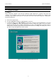
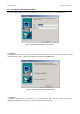
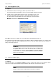
Instruction Manual 2.2 CyberComm CON 1500 User Name and Organisation Entry The CyberComm program (as below) prompts you to enter the name of the user and organization. Figure 2: CyberComm Pro Installation/ User Information See Figure 2. Follow the instruction in the subsequent menu for your desired location of this file to be saved. Make relevant changes until the setup is completed (shown below). Click on the Finish button. Figure 3: CyberComm Pro Installation/ Setup Complete See Figure 3.
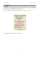
Instruction Manual 2.3 CyberComm CON 1500 Splash Screen See Figure 4. Upon clicking the Finish button, a splash screen pops up (shown below). The meter’s communication protocol setting i.e. baud rate, parity and stop bits must be properly set before you power the meter on. DO NOT press any key on the meter while the program is running. Go to the URL stated to download the latest FREE version of the CyberComm Pro software. Figure 4: Start up Menu Click OK to go to the following CyberComm Pro Main Menu.
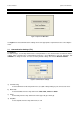
Instruction Manual 3 CyberComm CON 1500 CYBERCOMM PRO MAIN MENU Figure 5: CyberComm Main Menu See Figure 5. Select Communications Settings and set the appropriate requirements before connecting the meter. 3.1 Communication Settings (File) See Figure 6. To make changes, use the drop-down menu of each parameter to set to desired values to match the meter’s settings. After selecting proper communication parameters, select OK button to proceed. Otherwise click CANCEL if no change is made.
Instruction Manual 3.2 CyberComm CON 1500 Data Log Options (File) See Figure 7. a) Time between successive readings (1-3600 sec). Default is 10 sec. Select the time lag preferred between each successful reading using the arrow keys. b) Length of Time to Capture Data. Default is 0 min. (0= indefinitely, units = min) Select the total length of time preferred to capture data using the arrow keys. The data capture will automatically stop upon reaching the set amount of time.
Instruction Manual 4 4.1 CyberComm CON 1500 MAIN WINDOW (AFTER CONNECTING METER TO COMPUTER) CyberComm Pro Manuals (Help) See Figure 8 and 9. The main menu appears with the File and Help drop down menus, each having a list function settings shown below. Soft copies of the CyberComm Pro Software User Guide Manuals are available in the program itself. Select the manual option with reference to the meter you are using.
Instruction Manual CyberComm CON 1500 4.1.1 File Options (File) See Figure 10. Select File Options from the File drop down menu. Enter the relevant information for useful future references and type a file name/or file location that you wish to store these details. Click OK upon completion to save information. Figure 10: File Options 4.1.2 About CyberComm Pro (Help) See Figure 6. By selecting About CyberComm Pro from the Help drop down menu, the dialogue box will be shown as below.
Instruction Manual 4.2 CyberComm CON 1500 Sub menus & Function Icons on the CyberComm Program See Figure 12. The figure shows the CyberComm Pro software Main Menu after linking with the meter. From this menu, most of the meter key functions can be emulated except replatinisation of conductivity probe. This Sub Menu has following features: Figure 12: Running CyberComm Pro/ Complete Main Menu (Connected to meter) NOTE: All keys on the meter are disabled after connection to computer.
Instruction Manual 4.2.1 CyberComm CON 1500 Function Icons See Figure 13. See also Figure 12. The function icons on the main menu each serve a vital role in the CyberComm Pro software, providing user friendly one click access. Figure 13: Function Icon Panel (extracted from Figure 12) Icon no. Function Name Description 1 Record Click on this icon to start recording meter readings, readings will be shown on the CyberComm Pro main menu. Data captured will also be stored to the hard disk (in a “.
Instruction Manual CyberComm CON 1500 Figure 14: Record overwrite prompt Figure 15: Print screen 11
Instruction Manual CyberComm CON 1500 Icon 11: Meter Settings See Figure 16. Program your meter functions via this icon on CyberComm Program. a) Temperature I) Temperature Units of Measurement - Select °C or °F as required (Default is °C) II) Temperature Coefficient - Select from the range of 0.000 to 10.000 III) Normalised Temperature (°C/ °F) - Select from range of 15.0 to 30.0°C OR 59.0 to 86.
Instruction Manual CyberComm CON 1500 Continue from Section 4.2 Refer back to Figure 12 on page 9. 4.2.2 Measurement Mode This indicates the current mode of measurement of the meter, you can change the mode by selecting from the drop down menu to choose between the various parameters; Conductivity, Resistivity and TDS. 4.2.
Instruction Manual 4.3 CyberComm CON 1500 To quit CyberComm Program See Figure 18. Choose Exit from drop down menu of File or Click the ‘X’ button on the top right hand corner of the window. A pop-up menu will prompt you to save settings; select Yes if you want the settings you set to be available for next usage.
Instruction Manual 5 CyberComm CON 1500 RETRIEVE RECORDED DATA You are able to view the Recorded Data Readings in a Microsoft Excel© spreadsheet or on your Notepad©/ WordPad© etc. Steps to record and retrieve data in a measurement 1. Follow the steps in Section 3.2: Data Log Options (File) and enter the required information before a measurement you want to keep record of. Key in the desired time interval and measurement duration. 2.
Instruction Manual CyberComm CON 1500 Figure 20: Recorded Data in every 10 seconds displayed in Microsoft Notepad© 16
Instruction Manual 6 CyberComm CON 1500 EXPORT DATA READINGS You are able to view the Data Readings in a Microsoft Word© document, Microsoft Excel© spreadsheet or on your Notepad©, WordPad© etc. 6.1 Steps to export data readings from CyberComm Professional: While in measurement mode on the CyberComm Professional:1. Click the ‘Recall Memory’ button to view the recorded data readings 2. Select the ‘copy’ icon and the data readings will be copied to the ‘clipboard’ 3.
Instruction Manual 6.3 CyberComm CON 1500 Paste data in Microsoft Excel© , WordPad and Notepad Follow steps instructed in Section 6.1: Steps to export data readings from CyberComm Professional: and paste the data copied from the CyberComm Pro to a new document.
Instruction Manual CyberComm CON 1500 Figure 23: Paste data readings in a Microsoft Notepad© document 19
Instruction Manual 7 7.1 CyberComm CON 1500 PRINT READINGS Printing using a serial printer Connect the CyberScan CON 1500 bench meter to the serial printer via RS232C cable (refer to the list of accessories). The configuration of the RS232C port is as shown below. 7.
NOTES:
NOTES:
For more information on Eutech Instruments’ products, contact your nearest distributor or visit our website listed below: Eutech Instruments Pte Ltd. Blk 55, Ayer Rajah Crescent, #04-16/24 Singapore 139949 Tel: (65) 6778 6876 Fax: (65) 6773 0836 E-mail: marketing@eutechinst.com Web-site: www.eutechinst.