Instruction Manual CON 700 Conductivity/ºC/ºF Bench Meter Technology Made Easy ... Part of Thermo Fisher Scientific 68X541702 Rev.
TABLE OF CONTENTS 1. INTRODUCTION .............................................................. 1 2. GETTING STARTED........................................................ 2 2.1 2.2 2.3 Keypad Functions ................................................................... 2 LCD Annunciators ................................................................... 3 Meter Connections .................................................................. 3 3. ELECTRODE INFORMATION ....................................
6.12 CELL (Nominal Cell Constant) ................................................ 11 6.13 P4.0 rSt (Reset) ..................................................................... 12 6.14 P5.0 CLr (Clear Memory) ....................................................... 12 7. CALCULATING TDS CONVERSION FACTOR .............. 13 8. CALCULATING TEMPERATURE COEFFICIENTS........ 14 9. REPLACEMENTS AND ACCESSORIES........................ 15 10. TROUBLESHOOTING GUIDE......................................... 16 11.
1. INTRODUCTION Thank you for purchasing our Con 700 series benchtop meter. This microprocessor-based meter is economical and simple to use. The design incorporates a large LCD for clear viewing, yet offers a small footprint to conserve space. The CON 700 measures conductivity or TDS, and temperature (ºC or ºF) simultaneously. Each meter includes a convenient slide-out card for quick reference.
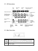
2. GETTING STARTED 2.1 Keypad Functions Powers the meter on and off. Upon power on, the meter automatically begins in the mode that was last used. Calibration and memory values are retained even if meter is unplugged. Toggle between available measurement modes— Conductivity with Temperature or TDS with Temperature. Also used to switch to Temperature calibration during Conductivity or TDS calibration mode. Press and hold for 5 seconds to enter SETUP mode. Toggles between measurement and calibration modes.
2.2 LCD Annunciators 2.
3. ELECTRODE INFORMATION The CON700 includes an electrode with a nominal cell constant of k = 1.0, built-in temperature sensor, and 1 meter cable. The Ultem body housing has good chemical resistant properties. The electrode design offers fast temperature response and reduces air entrapment, ensuring accurate, repeatable, and stable readings.
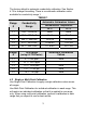
The factory default is automatic conductivity calibration. See Section 6.10 to change this setting. There is no automatic calibration value available for conductivity range 1. Range # r1 Conductivity Range TABLE 1 Automatic Calibration Values Normalization Temperature 0.00 – 20.00 μS 25 ºC 20 ºC None None r2 20.1 – 200.0 μS 84 μS 76 μS r3 200.1 – 2000 μS 1413 μS 1278 μS r4 2.01 – 20.00 mS 12.88 mS 11.67 mS r5 20.1 – 200.0 mS 111.8 mS 102.1 mS Range # TDS Range (using 0.
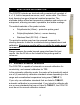
The factory default is Single-Point Calibration. See Section 6.11 to change this setting. 4.3 General Calibration Tips For best results, periodic calibration with known accurate standards is recommended. A maximum of one calibration point per range can be performed. If multiple calibration points are used in the same range, the most recent one will replace the previous one. When the electrode is replaced, it is best to clear the calibration to the factory default values (see Section 6.13).
4.5 Manual Conductivity & TDS Calibration Procedure 1) as needed to select conductivity (μS or mS) or TDS Press (ppm or ppt) calibration. 2) Dip the electrode into the calibration standard and press . Provide stirring for best results. The primary display will show the current reading, while the secondary display will be the factory default value. Adjust the 3) temperature reading using or . Press to accept.
2) Dip the probe into the sample beyond the upper steel band (utilize the fill line on the outside of the probe guard for reference). 3) Allow time for the reading to stabilize. Note the reading on the display. The clear yellow protective probe guard must be attached during measurement. Erroneous results will occur while the probe guard is removed. 5.2 Automatic and Manual Ranging The CON 700 automatically selects the optimum range in which your readings appear.
2) To recall data from memory, press . The location of the most recent stored data is displayed first. Press location of the desired data, then press or to select the to accept. 3) Press to return to the stored data location. Press to return to measurement mode. To erase stored data, see Section 6.14. 6. SETUP FUNCTIONS Use the set up mode to customize your instrument operation. During measurement, press and hold mode. Press or for 5 seconds to enter SETUP to change programs or change options.
Press to confirm. 6.5 P3.2 ºC ºF (Celcius Or Fahrenheit) Press . Press or Press to select ºC or ºF. to confirm. 6.6 P3.3 AtC (Automatic Temperature Compensation) Press . Press or Press to select “Yes” or “No”. to confirm. 6.7 P3.4 tdS (Total Dissolved Solids factor) Press . Press 1.00). or Press to select the desired TDS factor (.40 to to confirm. 6.8 P3.5 t.
Press . Press or Press to select the desired value (0.00 to 10.0). to confirm. 6.9 P3.6 t.nr (Normalization Temperature in ºC) When Automatic Temperature Compensation is used, measurements are adjusted by the temperature coefficient to the normalization temperature. The default value is 25 ºC. Press . Press or Press to select the desired value (15.0 to 30.0). to confirm. 6.10 ACAL (Automatic Conductivity Calibration) See Section 4.1 for more details on Automatic Conductivity Calibration.
performance in extreme sample ranges. Use this setup function to change the cell constant if necessary. Meter default is 1.0 to match the included probe. k = 0.1 ideal for low measurements <20 µS (<10 ppm). k = 1.0 ideal for mid-range measurements k = 10 ideal for high measurements >20 mS (>10 ppt). Press . Press or Press to select 0.1, 1.0, or 10.0 to confirm. 6.13 P4.0 rSt (Reset) Press . Press or to select “Yes” (Reset) or “No” (Cancel).
7. CALCULATING TDS CONVERSION FACTOR You can calibrate TDS using the value of the calibration standard solution at a standard temperature such as 25 ºC. To determine the conductivityto-TDS conversion factor use the following formula: Factor = Actual TDS ÷ Actual Conductivity @ 25 ºC Actual TDS: Value from the solution bottle label or as a standard made using high purity water and precisely weighed salts.
8. CALCULATING TEMPERATURE COEFFICIENTS To determine the temperature coefficient of your sample solution use this formula: Where: tc = Temperature coefficient 25 = 25 ºC CT1 = Conductivity at Temp 1 CT2 = Conductivity at Temp 2 T1 = Temp 1 T2 = Temp 2 NOTE: A controlled temperature water bath is ideal for this procedure. 1. 2. 3.
9. REPLACEMENTS AND ACCESSORIES Part number Ordering Code Item Description Eutech Instruments CON 700 Benchtop with electrode and integral stand,100/240 VAC ECCON70043S Replacement electrode, k = 1.0 Oakton Instruments 35411-00 CONSEN9501D 35608-74 Epoxy/platinum electrode, k = 0.1 - 35608-72 Glass/platinum electrode, k = 1.0 - 35608-76 Epoxy/platinum electrode, k = 10.
10. TROUBLESHOOTING GUIDE PROBLEM No display CAUSE SOLUTION Main power not switched on. AC Adapter socket not inserted properly. a) Switch on the power supply. “Ur” (Under range) Measured value is out of range. Check electrode is connected. “Or” (Over range) Electrodes not connected. Recalibrate the meter. Electrode clogged, dirty or broken. Confirm measurement condition. in primary or secondary display b) Re-insert AC Adapter. Clean or replace electrode. Meter not calibrated.
11. SPECIFICATIONS Conductivity Range TDS Range (0.5 TDS factor) 0 to 20.00, 200.0, 2000 µS 0 to 20.00, 200.0 mS 0 to 10.00, 100.0, 1000 ppm 0 to 10.00, 100.0 ppt (max 200.0 ppt @ 1.0 TDS factor) Resolution 0.05 % Full Scale Accuracy ±1% Full Scale Temperature Range (Meter) 0.0 to 100.0 ºC / 32.0 to 212.0 ºF Compensation Type & Range Automatic with supplied cell or Manual. 0.0 to 100 ºC / 32.0 to 212.0 ºF, 0.0 to 80 ºC / 32.0 to 176.0 ºF with supplied cell 0.1 ºC / ºF Resolution ± 0.5ºC / ± 0.
12. WARRANTY This meter is supplied with a warranty against significant deviations in material and workmanship for a period of THREE years from date of purchase whereas probe with a SIX month warranty. If repair or adjustment is necessary and has not been the result of abuse or misuse within the designated period, please return – freight prepaid – and correction will be made without charge. Eutech Instruments/Oakton Instruments will determine if the product problem is due to deviations or customer misuse.
For more information on our products, please contact our channel partner or visit our websites listed below: Oakton Instruments 625 E Bunker Court Vernon Hills, IL 60061 USA Tel: (1) 888-462-5866 Fax: (1) 847-247-2984 info@4oakton.com www.4oakton.com Eutech Instruments Pte Ltd Blk 55, Ayer Rajah Crescent, #04-16/24 Singapore 139949 Tel: (65) 6778 6876 Fax: (65) 6773 0836 eutech@thermofisher.com www.eutechinst.