
Instruction manual
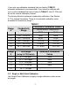
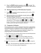
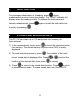
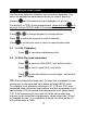
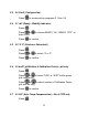
Table Of Contents
- 1. INTRODUCTION
- 2. GETTING STARTED
- 3. CONDUCTIVITY ELECTRODE
- 4. PH AND MV CALIBRATION
- 5. CONDUCTIVITY AND TDS CALIBRATION
- 6. CONDUCTIVITY AND TDS MEASUREMENT
- 7. HOLD FUNCTION
- 8. STORING AND RECALLING DATA
- 9. SETUP FUNCTIONS
- 9.1 1.0 CAL (Calibration)
- 9.2 2.0 ELE (Electrode Information)
- 9.3 3.0 ConF (Configuration)
- 9.4 3.1 rdY (Ready / Stability Indicator)
- 9.5 3.2 ºC ºF (Celsius or Fahrenheit)
- 9.6 3.3 buFF (pH Buffers & Calibration Points)—pH only
- 9.7 3.3 AtC (Auto Temp Compensation)—Con & TDS only
- 9.8 3.4 tdS (TDS factor)—Con & TDS only
- 9.9 3.5 t.CO (Temperature Coefficient)—Con & TDS only
- 9.10 3.6 t.nr (Normalization Temperature in ºC)—Con & TDS only
- 9.11 3.7 ACAL (Auto Conductivity Calibration)—Con & TDS only
- 9.12 3.8 SPC (Single Point Calibration)—Con & TDS only
- 9.13 3.8 CELL (Nominal Cell Constant)—Con & TDS only
- 9.14 4.0 rSt (Reset)
- 9.15 5.0 CLr (Clear Memory)
- 10. CALCULATING TDS CONVERSION FACTOR
- 11. CALCULATING TEMPERATURE COEFFICIENTS
- 12. REPLACEMENTS AND ACCESSORIES
- 13. TROUBLESHOOTING GUIDE
- 14. SPECIFICATIONS
- 15. WARRANTY
- 16. RETURN OF ITEMS
- info@4oakton.comwww.4oakton.com
6
tandard in which a meter/electrode system are
d
are
match the ORP value.
4.2 Millivolt (mV) Offset Adjustment
Oxidization Reduction Potential (ORP or Redox) is not a precise
measurement, but is useful as a relative indicator. As such, mV offset
adjustment is not meant to enhance accuracy, but rather to make
readings comparable to a reference. Commercial ORP solutions are
often used as a check s
verified to be close to a given value, instea of being used as a
calibration standard in which adjustments made in an attempt to
1) Con
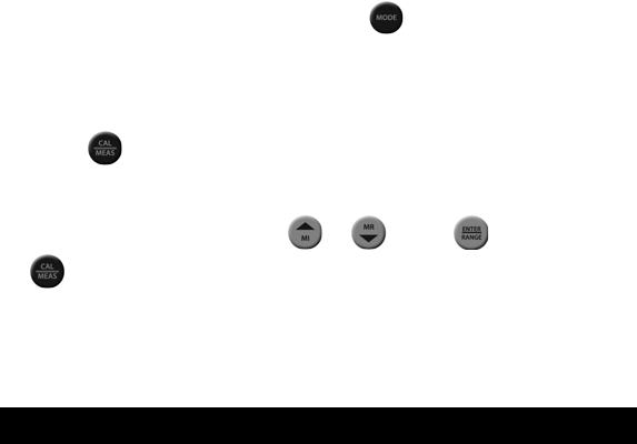
nect an ORP electrode and press as needed to select
(or R.mV).
mV
2) Dip the ORP el
ectrode into a solution with a known mV value
(i.e. Zobel, Light’s, quinhydrone, or iodidetriiodide) and stir.
3) Press when the reading is stable he prima display shows
the relative millivolt value (R.m ) whi he secon ry display sho
factory default mV value.
Adjust the R.mV value using
. T ry
V le t da ws
the
) or . Press 4 to accept or
to cancel. The meter allows an adjustable maximum value of
150
±
mV from the factory default mV value.
es
mV.
Note: When an offset has been stored successfully, R.mV replac
5. CONDUCTIVITY AND TDS CALIBRATION
5.1 Automatic or Manual Calibration
The PC 700 is capable of automatic or manual calibration for
conductivity, and manual calibration for TDS.
In the automatic calibration mode, the meter will automatically se
one of (4) conductivity calibration standard values depending on the
range and normalization temperature being used (TABLE 1).
lect