Instruction Manual PC 700 pH/mV/Conductivity/ºC/ºF Bench Meter Technology Made Easy ... Part of Thermo Fisher Scientific 68X541704 Rev. 1 Feb.
TABLE OF CONTENTS 1. INTRODUCTION .............................................................. 1 2. GETTING STARTED........................................................ 2 2.1 2.2 2.3 Keypad Functions ................................................................... 2 LCD Annunciators ................................................................... 3 Meter Connections .................................................................. 3 3. CONDUCTIVITY ELECTRODE ...................................
9.6 9.7 9.8 9.9 9.10 9.11 9.12 9.13 9.14 9.15 3.3 buFF (pH Buffers & Calibration Points)—pH only ............. 13 3.3 AtC (Auto Temp Compensation)—Con & TDS only .......... 13 3.4 tdS (TDS factor)—Con & TDS only ................................... 14 3.5 t.CO (Temperature Coefficient)—Con & TDS only............ 14 3.6 t.nr (Normalization Temperature in ºC)—Con & TDS only 14 3.7 ACAL (Auto Conductivity Calibration)—Con & TDS only .. 15 3.8 SPC (Single Point Calibration)—Con & TDS only ............. 15 3.
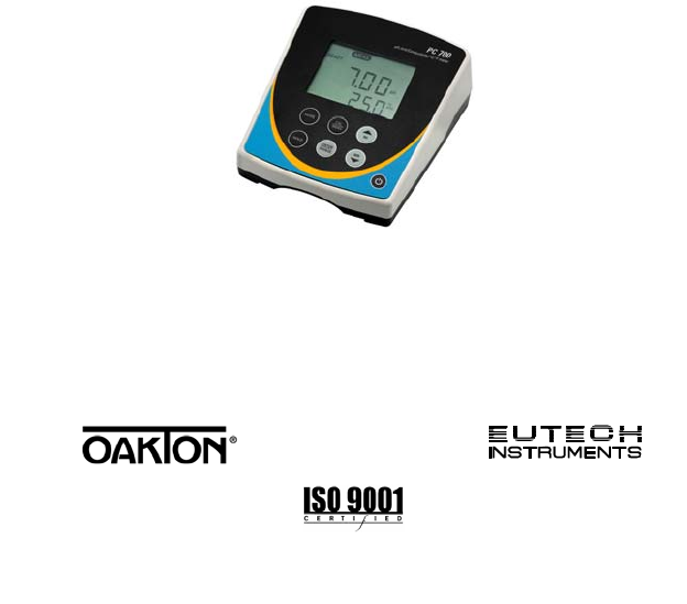
1. INTRODUCTION Thank you for purchasing our PC 700 series benchtop meter. This microprocessor-based meter is economical and simple to use. The design incorporates a large LCD for clear viewing, yet offers a small footprint to conserve space. The PC 700 measures pH, mV (ORP), conductivity, or TDS simultaneously with temperature (ºC or ºF). Each meter includes a convenient slide-out card for quick reference.
2. GETTING STARTED 2.1 Keypad Functions Powers the meter on and off. Upon power on, the meter automatically begins in the mode that was last used. Calibration and memory values are retained even if meter is unplugged. Toggle between available measurement modes— pH/Temp, mV/Temp, Conductivity/Temp, or TDS/Temp. Also used to switch to Temperature calibration during pH, mV, Conductivity or TDS calibration modes. Press and hold for 5 seconds to enter SETUP mode.
2.2 LCD Annunciators 2.
3. CONDUCTIVITY ELECTRODE The PC 700 includes an electrode with a nominal cell constant of k = 1.0, built-in temperature sensor, and 1 meter cable. The Ultem body housing has good chemical resistant properties. The electrode design offers fast temperature response and reduces air entrapment, ensuring accurate, repeatable, and stable readings.
USA buffer group 1.68, 4.01, 7.00, 10.01, 12.45 NIST buffer group 1.68, 4.01, 6.86, 9.18, 12.45 See Section 9.6 to change the buffer group 1) Press as needed to select pH. . The 2) Dip the pH and ATC electrodes into pH buffer and press secondary display will lock on the appropriate buffer value. Provide stirring for best results. When the READY indicator appears, press to accept. The primary reading will flash briefly before the secondary display begins scrolling the remaining available buffers.
4.2 Millivolt (mV) Offset Adjustment Oxidization Reduction Potential (ORP or Redox) is not a precise measurement, but is useful as a relative indicator. As such, mV offset adjustment is not meant to enhance accuracy, but rather to make readings comparable to a reference.
If you only use calibration standards that are listed in TABLE 1, automatic calibration is recommended. If you intend to calibrate with one or more standards that are not listed in TABLE 1, the PC 700 must be set for manual calibration instead. The factory default is automatic conductivity calibration. See Section 9.11 to change this setting. There is no automatic calibration value available for conductivity range 1.
Use Multi-Point Calibration for individual calibration in each range. This will restrict an individual calibration so that it is applied to one range only. When using multi-point calibration, perform a calibration in each range that you expect to use for best results. The factory default is Single-Point Calibration. See Section 9.12 to change this setting. 5.3 General Calibration Tips For best results, periodic calibration with known accurate standards is recommended.
4) When the READY indicator appears, press to accept. The primary reading will flash briefly before returning to measurement mode upon successful calibration. 5.5 Manual Conductivity & TDS Calibration Procedure 1) as needed to select conductivity (μS or mS) or TDS Press (ppm or ppt) calibration. 2) . Dip the electrode into the calibration standard and press Provide stirring for best results.
6. CONDUCTIVITY AND TDS MEASUREMENT 6.1 Taking Measurements 1) Rinse the electrode with de-ionized or distilled water before use to remove any impurities. Gently shake excess water droplets. 2) Dip the probe into the sample beyond the upper steel band (utilize the fill line on the outside of the probe guard for reference). 3) Allow time for the reading to stabilize. Note the reading on the display. The clear yellow protective probe guard must be attached during measurement.
7. HOLD FUNCTION For prolonged observation of a reading, press during measurement mode to freeze the display. The “HOLD” indicator will display when the reading is held. To release the held value and resume measurement, press memory by pressing 8. again or insert the held value into . STORING AND RECALLING DATA The PC 700 can retain up to 100 data points into memory for later retrieval. to insert the measured value 1) In the measurement mode, press into memory.
9. SETUP FUNCTIONS Use the setup feature to customize your instrument operation. First, select the appropriate measurement mode you wish to adjust by pressing until the desired units are displayed (i.e. pH, mV, for 5 Conductivity, or TDS). During measurement, press and hold seconds to enter SETUP mode of the parameter being measured. Press or to change programs or change options. Press to select the program or confirm selection. Press to go back one level or return to measurement mode. 9.1 1.
9.3 3.0 ConF (Configuration) Press to access set-up programs 3.1 thru 3.9. 9.4 3.1 rdY (Ready / Stability Indicator) Press . Press or Auto HOLd. Press to choose READY “On”, READY “OFF”, or to confirm. 9.5 3.2 ºC ºF (Celsius or Fahrenheit) Press . Press or to select ºC or ºF. to confirm. Press 9.6 3.3 buFF (pH Buffers & Calibration Points)—pH only Press . Press or to select “USA” or “NIST” buffer group (pH mode only). Press or to select number of Calibration Points (pH and Ion only).
Press or Press to select “Yes” or “No”. to confirm. 9.8 3.4 tdS (TDS factor)—Con & TDS only Press . Press 1.00). or Press to select the desired TDS factor (.40 to to confirm. 9.9 3.5 t.CO (Temperature Coefficient)—Con & TDS only The temperature coefficient is the amount of change in conductivity per degree temperature (% per ºC). The PC 700 is factory set to a temperature coefficient of 2.1 % per ºC. For most applications this will provide good results. The meter allows adjustment from 0.
Press . Press or to select the desired value (15.0 to 30.0). to confirm. Press 9.11 3.7 ACAL (Auto Conductivity Calibration)—Con & TDS only See Section 5.1 for more details on Automatic Conductivity Calibration. Press . Press or Press to select “Yes” (Automatic) or “No” (Manual). to confirm. 9.12 3.8 SPC (Single Point Calibration)—Con & TDS only See Section 5.2 for details on Single Point & Multi Point Calibration. Press . Press or Press to select “Yes” (Single) or “No” (Multi).
9.14 4.0 rSt (Reset) Press . Press or to select “Yes” (Reset) or “No” (Cancel). If “Yes”, press or to select “Cal” (calibration reset only) or “FCt” (complete reset to factory default settings). Press to confirm. 9.15 5.0 CLr (Clear Memory) Press . Press or Press to select “Yes” (Erase memory) or “No”. to confirm.
10. CALCULATING TDS CONVERSION FACTOR You can calibrate TDS using the value of the calibration standard solution at a standard temperature such as 25 ºC. To determine the conductivityto-TDS conversion factor use the following formula: Factor = Actual TDS ÷ Actual Conductivity @ 25 ºC Actual TDS: Value from the solution bottle label or as a standard made using high purity water and precisely weighed salts.
11. CALCULATING TEMPERATURE COEFFICIENTS To determine the temperature coefficient of your sample solution use this formula: Where: tc = Temperature coefficient 25 = 25 ºC CT1 = Conductivity at Temp 1 CT2 = Conductivity at Temp 2 T1 = Temp 1 T2 = Temp 2 NOTE: A controlled temperature water bath is ideal for this procedure. 1. 2. 3.
12.
13. TROUBLESHOOTING GUIDE PROBLEM CAUSE SOLUTION Main power not switched on. AC Adapter socket not inserted properly. Switch on the power supply. “Ur” (Under range) Measured value is out of range. Check electrode is connected. “Or” (Over range) Electrode not connected. Recalibrate the meter. Electrode clogged, dirty or broken. Confirm measurement condition. No display in primary or secondary display Re-insert AC Adapter. Clean or replace electrode. Meter not calibrated.
Calibration error. Buffer value does not match displayed value or electrode is disconnected or failing. Use fresh buffer solutions. Check electrode connection. Clean & recondition electrode. Replace electrode. Unstable pH reading Broken or worn electrode Replace electrode External ‘noises’ or induction (electrical ‘noise’ caused by a nearby motor) Remove or switch off interfering device Slow response Dirty electrode.
14. SPECIFICATIONS pH Range 0.00 to 14.00 pH Resolution 0.01 pH 0.01 pH + 1 count Accuracy Calibration Points Buffer Options Up to 5 points with Auto-buffer recognition USA : pH 1.68, 4.01, 7.00, 10.01,12.45 NIST: pH 1.68, 4.01, 6.86, 9.18 ,12.45 Slope Display Yes (with offset) 2000 mV mV Range Resolution Accuracy 0.1 mV ( 199.9 mV), 1 mV beyond 200 mV 0.2 mV ( 199.9 mV), 2 mV beyond 200 mV Offset Adjustment Conductivity Range TDS Range (0.5 TDS factor) Up to ±150 mV 0 to 20.
Cell Constant TDS Factor Calibration points 0.1, 1.0, 10.0 (selectable) 0.40 to 1.
15. WARRANTY This meter is supplied with a warranty against significant deviations in material and workmanship for a period of THREE years from date of purchase whereas probe with a SIX month warranty. If repair or adjustment is necessary and has not been the result of abuse or misuse within the designated period, please return – freight prepaid – and correction will be made without charge. Eutech Instruments/Oakton Instruments will determine if the product problem is due to deviations or customer misuse.
16. RETURN OF ITEMS Authorization must be obtained from our Customer Service Department or authorized distributor before returning items for any reason. A “Return Material Authorization” (RMA) form is available through our authorized distributor. Please include data regarding the reason the items are to be returned. For your protection, items must be carefully packed to prevent damage in shipment and insured against possible damage or loss.
For more information on our products, please contact our channel partner or visit our websites listed below: Oakton Instruments 625 E Bunker Court Vernon Hills, IL 60061 USA Tel: (1) 888-462-5866 Fax: (1) 847-247-2984 info@4oakton.com www.4oakton.com Eutech Instruments Pte Ltd Blk 55, Ayer Rajah Crescent, #04-16/24 Singapore 139949 Tel: (65) 6778 6876 Fax: (65) 6773 0836 eutech@thermofisher.com www.eutechinst.