
User Guide


Operating Instructions αlpha-RES1000
4
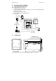
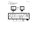
3.2 Back Panel
The back panel consists of two connectors. The first connector is the 17-way PCB edge connector and
the other is the 5-way connector.
Connection for the 17-way screw terminals (from left to right):
1. AC mains live wire 10. Alarm/Wash relay resting position (NO)
2. AC mains neutral wire 11. Alarm/Wash relay common
3. AC mains protective earth wire 12. Alarm/Wash relay working position (NC)
4. Relay 1 relay resting position (NC) 13. Hold function switch terminal 1
5. Relay 1 relay common 14. Hold function switch terminal 2
6. Relay 1 relay working position (NO) 15. No connection
7. Relay 2 relay resting position (NC) 16. 0/4 - 20 mA for -ve connection
8. Relay 2 relay common 17. 0/4 - 20 mA for +ve connection
9. Relay 2 relay working position (NO)
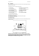
Connections for the 5-way screw terminals:
18. Pt1000/Pt100 lead 1 terminal (red)
19. Pt1000/Pt100 sense lead terminal (short 18 & 19 if using a two-wire system)
20. Pt1000/Pt100 lead 2 terminal (green)
21. Resistivity lead 1 (black)
22. Resistivity lead 2 (white)
*cable wire colours stated above are applicable to EC-CS10 series. For other electrodes, please check
electrode specifications.
IMPORTANT: The Alarm relay functions as an “Active Low” device i.e. it switches OFF under
Alarm condition. Therefore the Alarm display device should be connected to the ‘NC’ contacts of
the relay. If the relay is configured as “wash”, then it works in the ‘Active High’ mode. Therefore
the wash pump has to be connected across its “NO” contacts.
Pt100
/
RELAY1
LNPE
(F)
FUSE 250VAC
HOLD
ALARM
RELAY2
Pt1000
NC
-
+
cell
J2
100 mA