Instruction Manual αlpha-RES1000 Resistivity Controller/Transmitter Technology Made Easy ...
Preface This instruction manual serves to explain the use of the αlpha-RES1000 series Resistivity controller/transmitter. The manual functions in two ways: firstly as a step by step guide to help the user operate the instrument. Secondly, it serves as a handy reference guide. This instruction manual is written to cover as many anticipated applications of the αlpha-RES1000 Resistivity controller/transmitter.
Operating Instructions αlpha-RES1000 TABLE OF CONTENTS 1 INTRODUCTION .................................................................................................1 1.1 1.2 2 ASSEMBLY AND INSTALLATION.....................................................................2 2.1 2.2 3 4.1.1 4.1.2 4.2 4.3 5.1.1 5.1.2 5.2 5.2.1 5.2.2 Keypad .............................................................................................................. 5 Display ........................................
Operating Instructions 7.4.5 7.5 Maximum Pulse Length (tPL) or Maximum Frequency (FPF) ......................... 17 MEASUREMENT RANGE SUB-FUNCTION ...........................................................17 7.5.1 7.5.2 7.5.3 7.5.4 7.5.5 7.5.6 7.5.7 7.6 Entering the Measuring Range sub-function ................................................... 17 Selecting Measuring Range sub-function........................................................ 17 Measurement Range available in the Controller ..........
αlpha-RES1000 Operating Instructions 1 1.1 Introduction Description of Unit Thank you for purchasing Eutech’s ¼ DIN alpha-1000 series Resistivity process controllers. This unit is used for measuring the Resistivity of a solution in mega-ohms. You can use this unit to measure Resistivity with limit control. This controller has many user-friendly and safety features which include: • • • • • • • • • • • • • • • 1.
αlpha-RES1000 Operating Instructions 2 Assembly and Installation 2.
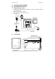
αlpha-RES1000 Operating Instructions 3 Electrical Connection 3.
αlpha-RES1000 Operating Instructions 3.2 Back Panel The back panel consists of two connectors. The first connector is the 17-way PCB edge connector and the other is the 5-way connector. Connection for the 17-way screw terminals (from left to right): 1. 2. 3. 4. 5. 6. 7. 8. 9.
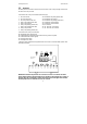
αlpha-RES1000 Operating Instructions 4 Overview 4.1 Keypad and Display 4.1.1 Keypad • Perform rapid calibration • • • • Allows entry to Set up mode Select individual functions within the function group of Set up mode Store input data in the Set up mode Start calibration in the calibration mode • Select various function groups in the Set up mode.
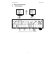
αlpha-RES1000 Operating Instructions 4.2 Function Groups The main function and sub-function groups are organised in a matrix format for configuration and selection of parameters.
αlpha-RES1000 Operating Instructions 4.3 Control Concept The main function and sub-function groups are organised in a matrix format as shown below. These functions can be accessed via the front keypad for configuration and selection of parameters.
αlpha-RES1000 Operating Instructions 5 5.1 Measurement Display in Measurement mode When controller is powered on, it automatically enters into the Measurement mode after large dual LCD briefly displays all segments. The upper display shows the measured Resistivity value, while lower display shows temperature value. Annunciators at right side of the display indicate mΩ and oC. Similarly annunciators or icons at the top or left side of the display shows current status of controller, e.g.
αlpha-RES1000 Operating Instructions NOTE: To view (not change) electrode condition, push ENTER key when the security code reads “000”. 5.2.1.1 Clearing Calibration security code from display The calibration security code automatically resets from “11” to “000” after returning to Measurement mode. 5.2.2 How to enter and change parameters in Advanced Setup mode 1) Press ENTER key once. Upper display shows “000” and lower display shows “S.Cd” to prompt for Advanced Setup security code.
αlpha-RES1000 Operating Instructions 6 Calibration Mode Calibration mode can be accessed directly from Measurement mode by pressing CAL key and entering the Calibration security code; or from the Advanced Setup mode. 6.1 Resistivity Calibration Calibration is always carried out in the specific range selected. The Resistivity Controller allows a onepoint calibration. 1) Enter Calibration mode. While in Measurement mode, press CAL key and scroll to Calibration code “11”. Press ENTER key.
αlpha-RES1000 Operating Instructions 7 7.1 Advanced Set-Up Mode Temperature Coefficient sub-function This sub-function allows you to select correct temperature coefficient for optimum operations. For applications in pure water or ultra-pure water industries, select “Pur” temperature coefficient option. For all other applications, select “Lin” temperature coefficient. Controller allows further input of temperature coefficient values, independently for process and for calibrating solutions.
αlpha-RES1000 Operating Instructions 7.2 Temperature calibration (ATC mode only) 1) Enter Advanced Set-up mode. Push the ENTER key and scroll to Advanced Set-up security code “22”. Push the ENTER key again. 2) Press the ∆ or ∇ keys to scroll through the sub-menus until the display shows “Set oC”. Press the ENTER key. Press the ∆ or ∇ keys to scroll until the upper display shows “ATC”, and the lower display shows “on”. Default setting is “ATC on”. 4) Press the ENTER key.
αlpha-RES1000 Operating Instructions 7) Continue with additional Advanced Set-up procedures, or return to Measurement mode by pressing ∆ and ∇ keys (escape) simultaneously. 7.3 Control Relay A/Control Relay B (SP1/SP2) sub-function SP1 option sets operating parameters for Relay A; and SP2 for relay B. Since these groups have the same set-up parameters, they are described together. HOLD SETUP HOLD SETUP SP 1 7.3.1 1) 2) HOLD SETUP HOLD SETUP 4) 5) HOLD SETUP Lo 0.20 0 0 SP 1 SP 1 HYS On.
αlpha-RES1000 Operating Instructions 4) Proceed to 7.3.4, or return Measurement mode by pressing ∆ and ∇ keys simultaneously (escape). 7.3.4 Selecting a hysteresis (dead band) value (0.000 to 0.200 mΩ or 0.00 to 2.00 mΩ) Hysteresis prevents rapid contact switching if the value is fluctuating near the set point. It does this by overshooting the set point value to a specified hysteresis value (default is 0.20 mΩ). You can set the hysteresis value from 0.000 to 0.200 mΩ or 0.00 to 2.00 mΩ.
αlpha-RES1000 Operating Instructions 7.3.6 Setting an off-delay time lag You can set as time delay for each relay, which stops the relay from switching off the moment the value reached the set point and hysteresis. This controller lets you set a 0 to 1999 seconds time delay before your relay deactivates. HOLD SETUP 1) Follow directions in 7.3.1 to enter Control Relay mode. 2) Push the ENTER key. The upper display shows “0” time and the OF.d lower display shows “OF.d”.
αlpha-RES1000 Operating Instructions 1) Follow directions in 7.4.1 to enter Controller mode. 2) Press the ENTER key. The upper display shows the current controller type and the lower display shows “tYP”. 3) 4) Press the ∆ and ∇ keys to select your controller type. L.Ct = limit value pickup (on/off control). oFF = controller off. PLC = pulse length control. PFC = pulse frequency control. Press the ENTER key to confirm your selection. 5) Proceed to 7.4.
αlpha-RES1000 Operating Instructions 7.4.5 Maximum Pulse Length (tPL) or Maximum Frequency (FPF) Note: If the controller type “oFF” or “L.Ct” is set, the parameters listed in 7.4.4 and 7.4.5 are blanked out. This mode lets you set the maximum pulse length or the maximum frequency at which the relay will operate. HOLD SETUP 1) Follow directions in 7.4.1 to enter Controller mode. 2) Press the ENTER key. Scroll until the lower display shows “t.PL” 10.0 or “F.PF”. t.
αlpha-RES1000 Operating Instructions 7.5.3 Measurement Range available in the Controller Range No. 1 2 Range 0.000 – 19.99 mΩ 0.00 – 1.999 mΩ Resolution 0.01 mΩ 0.001 mΩ Default cell K 0.01 0.1 7.5.4 Current Output (rng) sub-function This sub-function lets you set the transmitter current output range of this unit. The difference between the upper and lower range has to be a minimum of 20% of Full Scale, anywhere on the scale. 1) Follow directions in 7.5.2 to enter Controller mode.
αlpha-RES1000 Operating Instructions 7.5.7 Selecting Resistivity value at 20mA This parameter selects the resistivity value at which transmitter output will be 20mA. 4) Follow directions in 7.5.4 to enter Current Output mode. 5) Press the ENTER key until upper display shows a resistivity value and lower display shows “r.20”. 6) 7) 8) 7.6 Press the ∆ or ∇ keys to select the required resistivity value to be equivalent to 20 mA (Default is 20.00 mΩ).
αlpha-RES1000 Operating Instructions 7.6.3 Selecting the alarm time lag (if the relay 3 is set to Alarm) This parameter group lets you select a period of time before the alarm activates when your set point has been overshot. You can select from 0 to 1999 seconds. 1) Follow directions in 7.6.1 to enter Configuration mode. HOLD SETUP 2) Press the ENTER key until the upper display shows a numerical value (in seconds) and the lower display shows “AL.d”. 30 AL.
αlpha-RES1000 Operating Instructions 7.6.6 Input Line Resistance Adjust This function compensates for the line resistance of the cable to its cell. 1) Follow directions in 7.6.1 to enter Configuration mode. 2) Press ENTER key until upper display shows “0.0” and lower display shows “L.Ad”. L.Ad = line adjuster resistance (0.0 to 100.0) 3) 4) 7.6.7 HOLD SETUP 0.0 L.Ad Press ∆ or ∇ keys to input value. Press ENTER key. Proceed to 7.6.
αlpha-RES1000 Operating Instructions 8 Auto/Manual Mode Regardless of mode, control devices connected to Relay A or Relay B can be operated from front panel of controller. In Automatic mode, controller’s set point values activate relays. In Manual mode, manual control of relays is possible to prime the pump or check pump status. 8.1 Auto mode (mode after switch-on) To view set-point values: 1) Press RELAY SELECTION (Rel A/Rel B) key.
αlpha-RES1000 Operating Instructions 9 Technical Specifications Resistivity Range 0.00 to 19.99 mΩ/cm 0.000 to 1.999 mΩ/cm Resolution 0.01 mΩ/cm 0.001 mΩ/cm Default Cell Constant, K 0.01 0.
αlpha-RES1000 Operating Instructions Accessories Assembly Accessories Product Description Resistivity Cell, up to 20mΩ; Cell constant, K=0.01 with integrated Pt 100, Material SS316 and 25ft cable (open-ended) Resistivity Cell, up to 20mΩ; Cell constant, K=0.01 with integrated Pt 100, Material Titanium and 25ft cable (open-ended) – Ultrapure water applications Resistivity Cell, 0.10 – 2.00mΩ; Cell constant, K=0.
αlpha-RES1000 Operating Instructions 11 Appendices Appendix 1 – Jumper Positions Jumper Positions - Internal to the controller JP 1 Selects the input voltage 220 VAC. JP 2 Selects the input voltage 110 VAC. JP 6 Selects the temperature sensor for Pt1000/Pt100 Fuse Note that there is a fuse (slow-blow 100mA) internal to the controller. Before opening the unit, ENSURE that the power cable is physically separated from the power supply. Replace fuse with the recommended type only.
αlpha-RES1000 Operating Instructions Appendix 2 – Conductivity / Resistivity of Various Aqueous Solutions at 25oC Conductivity 0.05 uS/cm 0.05 - 1 uS/cm 0.5 uS/cm 0.1 - 10 uS/cm 1 - 80 uS/cm 10 uS/cm 0.5 - 1 mS/cm 0.9 - 9 mS/cm 1.
αlpha-RES1000 Operating Instructions Appendix 4 – Pure Water Curve Resistivity of Pure Water 100 90 80 70 60 50 40 30 20 10 0 0 5 10 15 20 25 30 35 40 45 50 55 Temp °C 27 60 65 70 75 80 85 90 95 100
For more information on Eutech Instruments products, contact your nearest Eutech Instruments distributor or visit our website listed below: Manufactured by: Eutech Instruments Pte Ltd. Blk 55 Ayer Rajah Crescent #04-16/24 Singapore 139949 Tel: (65) 6778 6876 Fax: (65) 6773 0836 E-mail: marketing@eutechinst.com Web-site: http://www.eutechinst.