
Instruction manual


6
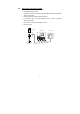
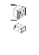
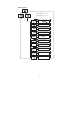
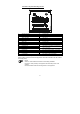
2.3.1 Display overview
The LC display shows two alpha-numerical fields for parameters and measured
values as well as various mode and status indicators.
MEAS
P
H%
SETUP
CAL
HOLD
O
C
s
p
h
atc
m
v
ready
err
O
f
Mode indicators:
– MEAS: Measurement mode
– SETUP: Set-up mode
– CAL: Calibration mode
Status indicators:
– READY: Visible after successful
calibration
– HOLD: Unit in “HOLD” mode
– ATC: Visible in ATC (Automatic
Temperature Compensation) mode. Not
visible in the Manual temperature
compensation mode. “ATC” flashes if the
temperature probe is faulty in its ATC
mode
– ERR: Error indicator
– S: Visible in symmetrical measurement
mode
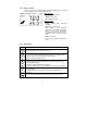
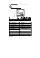
2.3.2 Key functions
Key
Description
– Enter Calibration mode (requires access code)
– Enter Set-up mode (requires access code)
– Access sub functions (parameters) within a function group of Set-up mode
– Confirm (store) set-up parameters and numerical values
– Start calibration in Calibration mode
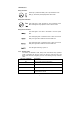
– Select function group in the Set-up mode.
– Set parameters and numerical values(if key is pressed continuously, the
setting speed increases)
– Control the relays in MANUAL relay operation
– Returns to “Measurement mode” when both keys are pressed simultaneously
– Display limit values for SP1 and SP2 and settings for wash contact in AUTO
relay operation
– Toggle between RELAY A, RELAY B or Wash relay in MANUAL relay
operation
– Switch from AUTO to MANUAL relay operation (requires access code)