Instruction Manual alpha-pH1000 pH and ORP Controller/Transmitter Technology Made Easy ... 68X216801 rev 1.
Instruction Manual alpha-pH 1000 Preface This manual serves to explain the use of the αlpha-pH1000 series pH/ORP controller/transmitter. The manual functions in two ways, firstly as a step by step guide to help the user operate the instrument. Secondly, it serves as a handy reference guide. This instruction manual is written to cover as many anticipated applications of the αlpha-pH1000 pH/ORP controller/transmitter.
Instruction Manual alpha-pH 1000 Safety Information The Eutech Controller/ Transmitter shall be installed and operated only in the manner specified in the Instruction manual. Only skilled, trained or authorized person should carry out installation, setup and operation of the instrument. Before powering up the unit, make sure that power source it is connected to, is as specified in the top label. Failure to do so may result in a permanent damage to the unit. The unit has live and exposed parts inside.
Instruction Manual alpha-pH 1000 TABLE OF CONTENTS 1 2 3 4 5 6 7 8 INTRODUCTION 5 1.1 1.2 5 5 Description of Unit Applications ASSEMBLY AND INSTALLATION 6 2.1 2.2 6 6 Measurement and Control System Unit Dimensions ELECTRICAL CONNECTION 7 3.1 3.2 7 9 Connection Diagram Back Panel OVERVIEW 10 4.1 4.2 4.3 10 11 12 Keypad and Display Function Groups Control Concept MEASUREMENT 13 5.1 5.2 13 13 Display in Measurement mode Security Codes CALIBRATION MODE 15 6.1 6.2 6.
Instruction Manual 1 INTRODUCTION 1.1 Description of Unit alpha-pH 1000 Thank you for purchasing Eutech’s ¼ DIN alpha-1000 series pH/ORP process controllers. This unit is used for measuring either pH or ORP parameter one at a time, and the operational mode is switchable from the menu. You can use this unit to measure pH or ORP with proportional or limit control. This controller has many user-friendly and safety features which include: • • • • • • • • • • • • • • • • • • 1.
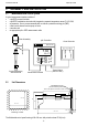
Instruction Manual 2 2.1 alpha-pH 1000 ASSEMBLY AND INSTALLATION Measurement and Control System A typical measurement system consists of: • a pH/ORP process controller • a pH/ORP combination electrode with integrated or separate temperature sensor Pt 100/1000, • an immersion, flow or process assembly with or without a potential matching pin (PMP) • a final control element such as pump or valve • a recorder and • an appropriate pH or ORP measurement cable.
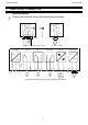
Instruction Manual 3 3.1 alpha-pH 1000 ELECTRICAL CONNECTION Connection Diagram Caution: Ensure electrical mains is disconnected before proceeding.
Instruction Manual alpha-pH 1000 Temp.
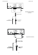
Instruction Manual 3.2 alpha-pH 1000 Back Panel Caution: Ensure electrical mains is disconnected before proceeding. The back panel consists of two connectors. The first connector is the 17-way PCB edge connector and the other is the 5-way connector. Connection for the 17-way screw terminals (from left to right): 1. AC mains live wire 10. Alarm/Wash relay working position (NO) 2. AC mains neutral wire 11. Alarm/Wash relay common 3. AC mains protective earth wire 12.
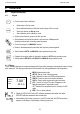
Instruction Manual 4 alpha-pH 1000 OVERVIEW 4.1 Keypad and Display 4.1.1 Keypad CAL • Perform rapid 2-point calibration • • • • Allows entry to Set up mode Select individual functions within the function group of Set up mode Store input data in the Set up mode Start calibration in the calibration mode • Select various function groups in the Set up mode.
Instruction Manual 4.2 alpha-pH 1000 Function Groups The main function and sub-function groups are organised in a matrix format for configuration and selection of parameters.
Instruction Manual 4.3 alpha-pH 1000 Control Concept The main function and sub-function groups are organised in a matrix format as shown below. These functions can be accessed via the front keypad for configuration and selection of parameters. MEASURE CODE OFFSET Set Offset SET oC Switch On/Off ATC Process temp. (MTC) Calib. temp.
Instruction Manual 5 5.1 alpha-pH 1000 MEASUREMENT Display in Measurement mode When the controller is initially powered on, it automatically enters into the Measurement mode after the large dual LCD displays all segments briefly. The upper display shows the measured pH or ORP value, while the lower display shows either the temperature value if the controller is set for pH measurement or “OrP” if it is set for ORP measurement.
Instruction Manual alpha-pH 1000 5.2.1 How to enter and change parameters in Calibration mode SETUP 1) Press the CAL key. The upper display shows “000” and the lower display shows “C.Cd” to prompt the user to enter the Calibration security HOLD code. C.Cd 2) Press the ▲ or ▼ key to scroll upper display to Calibration security code “11”. 3) Press the ENTER key. If configured for pH control, the display shows “CAL pH”. If configured for ORP control, the display shows “CAL OrP”.
Instruction Manual 6 alpha-pH 1000 CALIBRATION MODE You can reach the Calibration mode directly from the Measurement mode by pressing the CAL key and entering the Calibration security code. You can also reach the Calibration mode from the Advanced Setup mode. 6.1 pH Calibration This unit features 7 preset buffer values (1.01, 4.01, 6.86, 7.00, 9.00, 9.18 and 10.01) for fast auto calibration. When you calibrate this instrument, you need a standard pH buffer solution that matches one of these values.
Instruction Manual alpha-pH 1000 Note: If there is a calibration error, the controller displays “ERR”. If this happens, push both the ▲ and ▼ keys (escape) to restart the calibration beginning from step 1. Note: When calibrating with manual temperature compensation, the controller automatically changes from the preset process temperature to the calibration temperature.
Instruction Manual 6.3 alpha-pH 1000 ORP -% Calibration The ORP % mode allows you to calibrate at two points: a low concentration sample (20%) and a high concentration sample (80%). To calibrate the controller for ORP %: 1) Enter Calibration mode. While in Measurement mode, push SETUP the CAL key and scroll to Calibration Code “11”. Push the ENTER key. The upper and lower display reads “CAL OrP”. CAL HOLD 2) Note: If the upper and lower display read “CAL PH”, see OrP section 7.6.
Instruction Manual 7 7.1 alpha-pH 1000 ADVANCED SET-UP MODE Electrode Offset (OFS) sub-function You can perform electrode offset only in the pH mode. This mode allows you to change the offset parameter to make reading corrections without removing the electrode from the control system. You can make adjustments of up to +/- 120 mV. The controller will add or subtract the value from the measured pH and display the correct value.
Instruction Manual 7.2.2 alpha-pH 1000 Temperature calibration (ATC mode only) 1) Select “ATC on” as described above in Section 7.2.1. SETUP 2) Press the ENTER key. The upper display indicates the current temperature offset. The current measured temperature is shown in HOLD the lower display. Atc 3) Compare the current measured temperature on the controller display to a thermometer known to be accurate. Note down the correct temperature value.
Instruction Manual 7.3 alpha-pH 1000 Control Relay A/Control Relay B (SP1/SP2) sub-function The SP1 option sets the operating parameters for Relay A; the SP2 option sets the operating parameters for relay B. Since these groups have the same set-up parameters, they are described together. 7.3.1 Entering the Set point 1 (Set point 2) sub-function 1) Enter Advanced Set-up mode. Push the ENTER key and scroll to SETUP Advanced Set-up security code “22”. Push the ENTER key again.
Instruction Manual alpha-pH 1000 Follow directions in 7.3.1 to enter Control Relay mode. Press the ENTER key. Scroll with the ▲ or ▼ key until the upper HOLD display shows the hysteresis (dead band) value and the lower display HYS shows “HYS”. 3) Press the ▲ or ▼ keys to enter your hysteresis value for Set point 1 (Set point 2). Your controller will activate at the value you select. 4) Press the ENTER key to confirm your selection. 5) Proceed to 7.3.
Instruction Manual 7.4 alpha-pH 1000 Controller (Cntr) sub-function You can set the controller’s parameters in this sub-function. 7.4.1 Entering the Controller sub-function 1) Enter Advanced Set-up mode. Push the ENTER key and scroll to Advanced set-up security code “22”. Push the ENTER key again. 2) Press the ▲ or ▼ key to scroll until the upper display shows “Cntr”. SETUP HOLD SETUP SETUP HOLD L.Ct tyP HOLD Cntr SETUP oFF HOLD tyP SETUP PLC tyP HOLD PFC tyP 7.4.
Instruction Manual SETUP HOLD alpha-pH 1000 dEEn rEL SETUP HOLD En rEL 1) Follow directions in 7.4.1 to enter Controller mode. 2) Press the ENTER key. Scroll until the lower display shows “rEL” and the upper display shows the current selection (de-energised = dEEN or energised = EN). 3) Press the ▲ or ▼ key to choose de-energised or energised relay state. 4) Press the ENTER key to confirm your selection. 5) Proceed to 7.4.
Instruction Manual 7.5 alpha-pH 1000 Current Output (rng) sub-function SETUP HOLD rng SETUP HOLD 4-20 out SETUP HOLD 0 pH r.4 SETUP HOLD 14 r.20 pH This sub-function lets you set the controller current output range of this unit. 7.5.1 Entering current output sub-function 1) Enter Advanced Set-up mode. Push the ENTER key and scroll to Advanced Set-up security code “22”. Push the ENTER key again. 2) Press the ▲ or ▼ key to scroll until the upper display shows “rng”. 7.5.
Instruction Manual 7.6 alpha-pH 1000 Configuration (ConF) sub-function This group of parameters lets you configure the controller to suit your requirements. 7.6.1 Entering the Configuration sub-function 1) Enter Advanced Set-up mode. Push the ENTER key and scroll to Advanced Set-up security code “22”. Push the ENTER key again. 2) Press the ▲ or ▼ key to scroll until the upper display shows “ConF”.
Instruction Manual alpha-pH 1000 7.6.3 Selecting Alarm or Wash function This function allows you to use the Alarm relay as Wash contact. The Wash contact is used in combination with automatic cleaning systems. During the wash cycle, the analogue output is set on hold. SETUP Alr HOLD rL3 SETUP HOLD CLn 1) 2) 3) 4) Follow direction in 7.6.1 to enter Configuration mode. Press the ENTER key until upper display shows “Alr” or “CLn”. Press the ▲ or ▼ key to choose the desired function.
Instruction Manual 7.6.6 alpha-pH 1000 Configuring the Wash contact if relay 3 has been set to the Wash mode SETUP HOLD CLn rL3 SETUP HOLD 10.0 int SETUP HOLD 10 1) 2) 3) Follow directions in 7.6.1 to enter Configuration mode. Press the ENTER key until the upper display shows “Alr” or “CLn”. Press the ▲ or ▼ key to select the “CLn” function. Press the ENTER key. 4) Press the ▲ or ▼ key to select the wash cycle (int. 0.1 to 199.9 hours) and press ENTER.
Instruction Manual alpha-pH 1000 SETUP HOLD no dEF SETUP HOLD FCt dEF SETUP HOLD CAL dEF 7.7 1) 2) Follow directions in 7.6.1 to enter Configuration mode. Press the ENTER key until the upper display shows “no”, “FCt” or “CAL”, and the lower display shows “deF” (default). 3) Press the ▲ or ▼ key to select “no” for using the old values, “FCt” to reset all settings to factory defaults or “CAL” to reset calibration values only to the factory default values.
Instruction Manual 8 alpha-pH 1000 AUTO/MANUAL MODE Regardless of the mode, you can control devices connected to Relay A or Relay B from the front panel of this controller. In Automatic mode, the controller’s set point values activate the relays. In Manual mode, you have manual control of the relays so you can prime the pump or check pump status without operating the entire system. 8.1 Auto mode (mode after switch-on) In this mode, the controller set-point values activate the relays.
Instruction Manual 9 alpha-pH 1000 TECHNICAL SPECIFICATIONS pH Range Resolution Relative Accuracy mV Range Resolution Relative Accuracy Temperature Resolution Relative Accuracy Sensor Temperature Compensation Set-point and Controller Functions Function (switchable) Controller characteristics Adjustable period with pulse length controller Adjustable period with pulse frequency controller Pickup / Dropout delay Switching pH hysteresis Switching ORP hysteresis Contact outputs, controller Switching voltage /
Instruction Manual alpha-pH 1000 Mechanical Specifications Dimensions (control panel housing - L x H x W) Weights (control panel housing) Material Insulation (Front / Housing) 175 x 96 x 96 mm max. 0.
Instruction Manual alpha-pH 1000 10 ACCESSORIES Replacement Unit Product Description αlpha-pH1000 pH/ORP Controller/Transmitter with 0/4-20 mA output and 110VAC Setting αlpha-pH1000 pH/ORP Controller/Transmitter with 0/4-20 mA output and 220VAC Setting Code no.
Instruction Manual alpha-pH 1000 11 GENERAL INFORMATION 11.1 Warranty Eutech Instruments warrants this product to be free from significant deviations in material and workmanship for a period of one year from the date of purchase. If repair is necessary and has not been the result of abuse or misuse within the warranty period, please return by freight pre-paid and amendment will be made without any charge. Eutech Instruments’ Customer Service Dept.
Instruction Manual alpha-pH 1000 12 APPENDICES 12.1 Appendix 1 Before opening the unit, ENSURE that the power cable is physically separated from the power supply. Jumper Positions - Internal to the controller JP 1 Selects the input voltage 220 VAC. JP 2 Selects the input voltage 110 VAC. JP 3 Selects between Pt100 and Pt1000. Fuse Note that there is a fuse (slow-blow 100mA) internal to the controller. Replace fuse with the recommended type only.
Instruction Manual 12.2 alpha-pH 1000 Appendix 2 The following table shows the various pH values at different temperature of the solution during calibration. Temperature (oC) 0 5 10 15 20 25 30 35 40 45 50 55 60 70 80 90 pH 1.00 0.96 0.99 0.99 0.99 1.00 1.01 1.01 1.01 1.01 1.01 1.01 1.01 1.02 1.02 1.02 1.02 pH 4.01 4.01 4.01 4.00 4.00 4.00 4.01 4.01 4.02 4.03 4.04 4.06 4.08 4.10 4.12 4.16 4.20 pH 6.86 6.98 6.95 6.92 6.90 6.88 6.86 6.85 6.84 6.84 6.83 6.83 6.83 6.84 6.85 6.86 6.88 35 pH 7.00 7.12 7.
Instruction Manual 12.3 alpha-pH 1000 Appendix 3 Simple Explanation on the Function of Hysteresis SP1 Set to LO SP2 Set to HI RELAY ON RELAY OFF 4.0 4.5 7.0 SP1 FORWARD DIRECTION 9.5 10.0 SP2 HYSTERESIS BAND (DEFAULT = 0.5 pH) REVERSE DIRECTION The controller relay activates when the set-point is reached. In the reverse direction, it does not de-activate when the value reaches the set-point. Instead, it continues to be active till the value reaches the amount set by the Hysteresis band.
Instruction Manual 12.4 alpha-pH 1000 Appendix 4 General Instructions Concerning Controller Setting MIN Function MAX Function Yh 100 % 50 % 0% - Xw + Xw Xp Xp Prop. Band SP 1 Prop.
Instruction Manual alpha-pH 1000 The output relay of the pulse length controller is clock-timed. The switching period T remains constant. Depending on the divergence from the limit value, the switch-on time tON is increased or decreased in accordance with the proportional range Xp. The following applies: tON + tOFF = T (Const.
Instruction Manual NOTES: alpha-pH 1000
For more information on Eutech Instruments products, contact your nearest Eutech Instruments distributor or visit our website listed below: Manufactured by: Eutech Instruments Pte Ltd. Blk 55, Ayer Rajah Crescent, #04-16/24 Singapore 139949 Tel: (65) 6778 6876 Fax: (65) 6773 0863 E-mail: marketing@eutechinst.com Web-site: http://www.eutechinst.