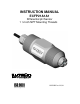
INSTRUCTION MANUAL ECFP21A1A1 Differential pH Sensor 1 ½ Inch NPT Mounting Threads Technology Made Easy ...
Preface This instruction manual serves to explain the use of the ECFP21A1A1 1½ inch pH sensor and is written to cover as many applications as possible. Please do not hesitate to contact Eutech Instruments or an authorized representative with questions or concerns. The information presented in this instruction manual is subject to change without notice as improvements are made, and does not represent any commitment whatsoever on the part of Eutech Instruments.
Safety Information The ECFP21A1A1 1½ inch pH sensor shall be installed and operated only in the manner specified. Only a skilled, trained or authorized person should carry out installation, setup and operation of the sensor system. Before using the sensor, make sure that the sensor cable is connected as specified. Failure to do so may result in permanent damage to the sensor or controller. Protection against electric shock will be achieved only by observance of the corresponding installation rules.
TABLE OF CONTENTS 1. INTRODUCTION................................................................................................................................... 1 1.1. 1.2. 2. PRODUCT DESCRIPTION .................................................................................................................. 3 2.1. 2.2. 3. GENERAL INFORMATION .................................................................................................................... 1 INTENDED USE .........................
Instruction manuals ECFP21A1A1 1. INTRODUCTION 1.1. General Information Thank you for purchasing the ECFP21A1A1 Differential pH Sensor. This industrial sensor has many enhanced features that offer superior performance in process applications: • Differential pH measurement technology minimizes susceptibility to ground loops. • A built in pre-amplifier eliminates high impedance wiring problems. • A replaceable heavy-duty quad junction salt bridge for extended life in severe applications.
Instruction manuals ECFP21A1A1 1.2. Intended use ECFP21A1A1 1½ inch pH sensor is designed to continuously measure pH and temperature in aqueous solutions in accordance with the technical product specifications in Section 2.2 of this manual. Any other use, or use not mentioned here, that is incompatible with the technical specifications is deemed inappropriate. The operator is solely responsible for any damage arising from such use.
Instruction manuals ECFP21A1A1 2. PRODUCT DESCRIPTION 2.1. Sensor Description The ECFP21A1A1 1½ inch pH sensor uses a differential measurement technique to maximize lifetime in continuous industrial applications. The ground rod and encapsulated preamplifier construction reduce the effects of ground loops and allow the pH signals to be transmitted up to 3,000 feet. A replaceable heavyduty quad junction salt bridge makes it simple to refurbish the sensor when necessary.
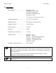
Instruction manuals ECFP21A1A1 2.2. Specifications Wetted Materials……………………………. Sensor Body - CPVC Salt Bridge Junctions - Kynar® pH Electrode - General glass Ground Rod - 316 Stainless Steel O-Ring Seals - Viton® (Consult factory for customized material construction) Operating Temperature…………………….. -5°C to 95°C (23°F to 203°F) Maximum Pressure…………………………. 100 psi @ 100°C (100 psi @ 212°F) Maximum Flow Rate………………………...
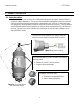
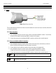
Instruction manuals ECFP21A1A1 3. INSTALLATION 3.1. Wiring Figure 3.1: pH Sensor Hook Up There are two different methods for electrical connection between the sensor and the pH controller; either direct or through a junction box. 3.1.1. Direct Connection 1. Use a watertight cord grip to insert the sensor cable into the Alpha pH2000D Controller. Conduit holes are found on the bottom of the Alpha pH2000D controller for this purpose. 2.
Instruction manuals ECFP21A1A1 3.2. Mounting Hardware Eutech Instruments’ short nose sensor (Fig 3.2) has insertion threads located closer to the sensing elements and is recommended for short branch tees (typically metal tees and SCH 40 plastic tees). Save the protective cap and use it to keep electrodes moist whenever the sensor is removed from service. When taking a sensor out of storage, soak the sensor in a pH 7 buffer solution for 30 minutes before calibration.
Instruction manuals ECFP21A1A1 3.2.1. Pipe Tee Mounting Eutech Instruments’ distinct body type for its 1½ inch differential pH sensor ensure optimal positioning of the active pH sensor electrode in the process flow. Normally available pipe tees vary widely in construction dimensions. CPVC pipe tees are most generally available with schedule 80 walls. Stainless steel tees have thinner walls that change the final position of the sensor. Common mounting arrangements are shown for the short nose pH sensors.
Instruction manuals ECFP21A1A1 Acceptable Tee Mounting Configuration for Specific Applications The short nose sensor bodies can be installed in a variety of tee pipes but optimal electrode positioning may not be maintained. If the sensor body does not extend far enough it may be possible for an air pocket to form. Alternatively, if the sensor body extends past the midway point it may restrict flow. As long as precautions are taken these setups can be used. Dimensions: IN (mm) Figure 3.
Instruction manuals ECFP21A1A1 Detailed Pipe Tee Installation Instructions 1. Wiring: a. Route the cable – either through conduit or on a cable tray. b. Insert the sensor cable into the Alpha pH2000D controller through a watertight cord grip. Conduit holes are provided for the cord grip on the bottom of the Alpha pH2000D controller. c. Connect the sensor wires into the Alpha pH2000D sensor terminal block as shown in the Alpha pH2000D manual. 2. a. b. c. d. 3.
Instruction manuals ECFP21A1A1 3.2.2. Immersion Mounting For immersion mounting applications the sensor is connected to a 1½ inch extension pipe to protect the cable from damage and to reduce the possibility of leaks that may damage the sensor. Figure 3.
Instruction manuals ECFP21A1A1 Detailed Insertion Mount Installation Instructions 1. Wiring: a. Route the sensor cable through the 1.5 inch extension pipe. b. Apply Teflon® tape to the sensor threads. c. Attach the sensor to the 1.5 inch NPT coupling by turning the sensor in a clockwise direction until secure. d. Either route the cable directly to the Alpha pH2000D or splice the wires in a junction box and use an extension cable. e.
Instruction manuals ECFP21A1A1 4. pH SENSOR MAINTENANCE 4.1. Cleaning the pH Sensor Head 4.1.1. In order to maintain an accurate measurement value, the sensor will need occasional maintenance. The maintenance interval will be dictated by the process in which it is installed. The harsher the process, the more often the sensor will require maintenance. Regular maintenance will yield a longer sensor life. 4.1.2. The sensor cleaning procedure is as follows: 4.1.2.1.
Instruction manuals ECFP21A1A1 4.2. pH Sensor Refurbishment - Replacing the Salt Bridge and Reference Solution 4.2.1. If the sensor head has been cleaned (see section 4.1.2) and calibration cannot be achieved, replace the salt bridge and reference solution. 4.2.2. Hold the sensor firmly with the electrode tip facing upwards. Remove the existing salt bridge by using a 15/16 wrench (24mm) and turning it counterclockwise. Dispose of the salt bridge using an approved method. 4.2.3.
Instruction manuals ECFP21A1A1 4.3. pH Sensor Troubleshooting General Inspection If the sensor is not providing reasonable signals to the analyzer, check the following: 1. Inspect the integrity of the glass electrodes. If the electrode is broken, replace the sensor. 2. Inspect the integrity of the salt bridge junctions. Be sure that they are clean and moist. If the salt bridge has been allowed to dry out it may be necessary to replace the salt bridge and filling solution. 3.
Instruction manuals ECFP21A1A1 pH Offset Test 1. Disconnect the RED and GREEN sensor wires from the analyzer terminal block while leaving the other wires connected. Connect the (+) lead of a millivolt meter to the RED wire and the (-) lead of the millivolt meter to the GREEN wire. 2. Put the sensor in 7 pH buffer. Stir the sensor for 10 to 15 seconds and then allow the sensor to stabilize in solution for about 2 minutes. The meter should read 0.0mV +/- 50 mV.
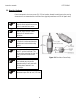
Instruction manuals 5 ECFP21A1A1 pH SENSOR SPARE PARTS and ACCESSORIES 5.1.1 Reference Cell Replacements Description • Reference Cell Solution (500 ml) • Protected PEEK® Salt Bridge (O-ring included) • Flat PEEK® Salt Bridge (O-ring included) • Protected CPVC Salt Bridge (O-ring included) • Flat CPVC Salt Bridge (O-ring included) • pH Sensor Storage Solution • Protective Cap 5.1.
Instruction manuals ECFP21A1A1 5.1.
Instruction manuals 6 ECFP21A1A1 WARRANTY The ECFP21A1A1 1½ inch pH sensor is supplied with a 6 month warranty against manufacturing defects. If repair or adjustment is necessary and has not been the result of abuse or misuse within the designated period, please return – freight pre-paid – and correction will be made without charge. Eutech Instruments will determine if the product problem is due to deviations or customer misuse. Out of warranty products will be repaired on a charged basis.
Instruction manuals 7 ECFP21A1A1 RETURN OF ITEMS Authorization must be obtained from our Customer Service Department or authorized distributor before returning items for any reason. A “Return Goods Authorization” (RGA) form is available through our Authorized Distributor. Please include data regarding the reason the items are to be returned. For your protection, items must be carefully packed to prevent damage in shipment and insured against possible damage or loss.
For more information on Eutech Instruments products, contact your nearest distributor or visit our website listed below: Eutech Instruments Pte Ltd Blk 55, Ayer Rajah Crescent, #04-16/24 Singapore 139949 Tel: (65) 6778 6876 Fax: (65) 6773 0836 E-mail: marketing@eutechinst.com Web-site: www.eutechinst.