Instruction Manual pH 500 LCD Transmitter 2-wire pH/ORP Transmitter with Display Technology Made Easy ...
Preface This manual serves to explain the use of the pH 500 transmitter. It functions in two ways, firstly as a step by step guide to help you to operate the transmitter. Secondly, it serves as a handy reference guide. It is written to cover as many anticipated applications of the transmitter as possible. If there are doubts in the use of the transmitter, please do not hesitate to contact the nearest Authorized Distributor.
TABLE OF CONTENTS 1 INTRODUCTION 1 2 2.1 2.2 PREPARATION Power Supply Requirements Connecting the Electrode and Temperature Probe 2 3 3 3.1 3.2 INSTALLATION Wall Mount Panel Mount 4 5 4 4.1 4.2 DISPLAY AND KEYPAD FUNCTIONS Display Keypad 6 7 5 5.1 5.2 5.3 5.4 CALIBRATION Preparing the Transmitter for Calibration pH Calibration Relative mV Calibration Temperature Calibration 8 9 10 10 6 6.1 6.2 6.3 6.4 6.5 6.
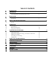
1 INTRODUCTION Thank you for selecting a Eutech Instruments/ Oakton Instruments transmitter. The pH 500 pH/ORP Transmitter is a microprocessor-based instrument that is designed to be sturdy and user-friendly. It is capable of measuring pH, mV and temperature. This transmitter has many user-friendly features – all of which are completely accessible through the water-resistant membrane keypad. Your transmitter includes an instruction manual and a warranty card.
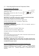
Preparation Remove screws from the four corners at the back of the Transmitter, and remove back cover. Connectors should be exposed as follows: All wiring is done on the detachable 9-pin connector. Using a suitable screwdriver, loosen screws from top of connector. When inserting the wires, always hold connector with top screws facing up. 1.1 Power Supply Requirements This transmitter requires a 12 to 24V DC power supply. Other Transmitters and/or a chart recorder may be connected in series.
1.2 Connecting the Electrode and Temperature Probe To connect the pH or ORP electrode: The Eutech Instruments pH transmitter uses any standard pH or ORP. Remove BNC connector from cable. Two wires will be exposed: pH reference Clear sheath pH sensing Insulation Screen Strip insulation, just enough to expose bare wires. IMPORTANT: For pH/ORP sensing cable, remember to strip the inner black layer (screen) and expose the clear plastic sheath. Insert pH sensing cable into pin 9 of connector. Tighten screw.
2 2.
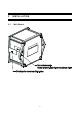
2.2 Panel Mount 1. Prepare panel cut-out of 92.0 mm by 92.0 mm Panel (side) 2. Remove back cover of transmitter and slide it through panel cut-out 4. Thread rods through lugs until transmitter is held in place against panel 3.
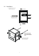
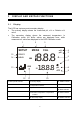
3 DISPLAY AND KEYPAD FUNCTIONS 3.1 Display The LCD has a primary and secondary display. • The primary display shows the measured pH, mV or Relative mV value. • The secondary display shows the measured temperature. In Calibration mode, pH buffer values are displayed here; while measured mV values are displayed in the ORP Calibration mode. 15 14 1 2 SETUP MEAS READY HOLD 12 1. SETup mode indicator 2. MEASurement mode indicator 3. CALibration indicator CAL -.8.8.8 ERR 13 3 -1.8.8.
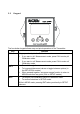
3.2 Keypad The four-button keypad allows easy and quick operations of the Transmitter. Key Function CAL Brings you directly into the Calibration mode. 1. If you were in pH Measurement mode, press CAL to enter pH Calibration mode. 2. If you were in mV Measurement mode, press CAL to enter mV Calibration mode. ▲/▼ 1. 2. 3.
4 CAL IBRATION 4.1 Preparing the Transmitter for Calibration Before starting calibration, make sure you are in the correct measurement mode. When you switch on the transmitter, the transmitter starts up in the units last used. For example, if you shut the transmitter off in “mV” units, the transmitter will read “mV” units when you switch the transmitter on. Be sure to remove the protective electrode storage bottle or rubber cap of the electrode before calibration or measurement.
4.2 pH Calibration A complete 2-point CAL is required for this Transmitter. If Calibration is aborted after 1st calibration point, transmitter reverts to previous Calibration data. 1. Rinse probe thoroughly with de-ionized water or a rinse solution. Blot excess liquid. CAL READY 2. 3. Dip probe into calibration buffer. End of probe must be completely immersed into buffer. Stir probe gently to create a homogeneous sample. From pH MEAS mode, press CAL to enter pH calibration mode.
4.3 Relative mV Calibration CAL R.mV 1. READY HOLD CAL R.mV READY HOLD CAL READY HOLD 4.4 From the ORP MEAS mode, press CAL key. CAL indicator appears at top of LCD. Primary display shows relative mV reading and secondary display shows absolute mV value. NOTE: If you have never calibrated relative mV or if the transmitter has been reset, the value shown in the primary display is the same as the absolute mV value. 2.
5 ADVANCED SETUP FUNCTIONS The advanced setup mode lets you customize your transmitter’s preferences and defaults. This transmitter features different sub groups that organize all setup parameters. The sub-groups are: 5.1 Offset Setting (Unavailable in ORP mode) As a result of the continuous measurement and the application concerned, it may not be convenient to remove the electrode for calibration. In such cases, an on-line Offset adjustment is offered. 1. Press ENT key. Transmitter displays ‘OFS’.
5.2 Output Range Setting Output of pH 500 transmitter is via the 2-wire power supply loop. Both the 4 mA and 20 mA output can be assigned to specific pH or ORP values, for a more refined output. SETUP HOLD 1. Press ENT key and use ▲ or ▼ keys to scroll till LCD displays ‘r n g ’. Press ENT again. Upper display shows pH value, ‘0.00’ (or – 1000 mV) while lower display shows ‘r 4.0’. 2. Assign pH or ORP value to 4 mA output current. Use ▲ or ▼ keys to change pHor ORP value. Press ENT to accept value.
5.3 Temperature Compensation Setting (Unavailable in ORP mode) pH values other than pH 7.00 is affected by temperature. Under varying temperature conditions, use ATC to compensate pH values. If temperature of bath is constant, then select Manual Temperature Compensation. 5.3.1 Automatic Temperature Compensation For automatic temperature compensation (ATC), connect ATC probe to transmitter, as described in Section 3.2, page 5. 1. Press ENT key to enter SETUP mode.
4. Use ▲ or ▼ keys to set temperature of sample. Press ENT key. 5. Primary display shows temperature (default is 25.0), and secondary display shows ‘C o C’. Input temperature of your calibration solutions. Press ENT key. 6. Press S and T keys together, to return to MEAS mode. The transmitter will now compensate pH readings for the manually set temperature (values taken from P oC). SETUP HOLD SETUP SETUP HOLD HOLD SETUP SETUP HOLD . . HOLD 癈 . ATC SETUP HOLD .
5.4 HOLD Current Setting SETUP When Transmitter is in CAL or SETUP modes, it automatically goes into a HOLD ‘HOLD’ mode. To indicate Transmitter is in ‘HOLD’ mode, output current can be set to 22 mA output by activating the ‘HLD On’. 1. SETUP HOLD Press ENT key and use ▲ or ▼ keys to scroll till LCD displays ‘SEt’ in the upper display; and ‘HLd’ in the lower display. Press ENT again. 2. Upper display now shows ‘HLd’. Lower display will show either ‘OFF’ or ‘On’.
5.6 Configuration 5.6.1 Selecting pH or ORP Mode of Operation The alpha pH 500 transmitter is not only a pH transmitter, but also an ORP SETUP transmitter. When configured to measure ORP, electrode must be changed HOLD and calibrated (see Section 5.3 for calibration procedure). ORP values are measured and displayed in mV only. 1. 2. Press ENT key and use ▲ or ▼ keys to scroll till LCD displays ‘COF’ (Configuration). Press ENT again. LCD displays ‘PH’.
6 PROBE CARE AND M AINT ENANCE Since your pH electrode is susceptible to dirt and contamination, clean it every one to three months depending on the extent and condition of use. NOTE: For specialty electrode care, consult the instruction manual included with your electrode. pH electrode storage For best results, always keep the pH bulb wet. Use the protective electrode storage bottle or rubber cap filled with electrode storage solution to store your electrode.
• Protein deposits: Prepare a 1% pepsin solution in 0.1 M of HCl. Set the electrode in the solution for five to ten minutes. Rinse the electrode with distilled water. Reactivating the pH electrode If stored and cleaned properly, your pH electrode should be ready for immediate use. However, a dehydrated bulb may cause sluggish response. To rehydrate the bulb, immerse electrode in a pH 4 buffer solution for 10 to 30 minutes. If this fails, the electrode requires activation.
7 TROUBLE SHOOTING GUIDE Problem Cause Solution Power on but no display a). Loose connections a). Check cables are making good contact. b). Cables not in correct polarity (+ and – position). b). Re-wire loop cables with correct polarity. a). Air bubbles in probe. a). Tap probe to remove bubbles. b). Dirty probe. b). Clean the probe and re-calibrate. c). Probe not deep enough in sample. c). Make sure sample entirely covers the probe sensors. Unstable readings d).
8 SPECIFICATIONS SPECIFICATIONS DESCRIPTIONS pH Range 0.00 to 14.00 pH Resolution / Accuracy 0.01 pH / ± 0.01 pH -10.0 to 110.0 °C Temperature Range Resolution / Accuracy Millivolt Range 0.1 °C / ± 0.5 for °C -1000 to +1000 mV 1 mV / ± 2 mV Resolution / Accuracy Temperature Compensation Auto (Pt 100) / Manual (from 0 to 100 °C) Number of calibration points 2 Number of calibration buffers USA: 4.01, 7.00, 10.01; NIST: 4.01, 6.86, 9.18 Inputs Asymmetrical / Symmetrical Output 4.0 to 20.
9 TE CHNICAL DIM ENS IONS 21
10 ACCE SS ORIES EUTECH INSTRUMENTS Replacement Transmitter and Transmitter accessories Ordering Code No.
OAKTON INSTRUMENTS Replacement Transmitter and Transmitter accessories Ordering Code No. Item Alpha pH/ORP 2-wire LCD Transmitter Combination pH electrode with 5m cable Combination pH electrode with PMP and 5m cable Combination pH electrode with PT 100, PMP and 5m cable Combination pH electrode, submersible, with 5m cable Combination Gold ORP electrode with PMP and 5m cable Combination Platinum ORP electrode with PMP and 5m cable Calibration Solutions Ordering Code No. Item pH 4.
11 WARRANT Y This transmitter is supplied with a one-year warranty against significant deviations in material and workmanship from date of purchase and a six-month warranty for probe. Each instrument will have a warranty card with a specific serial number. The warranty card must be endorsed by the Authorized Distributor at the point of sale.
For more information on our products, contact your nearest distributor or visit our website listed below: Eutech Instruments Pte Ltd. Blk 55, Ayer Rajah Crescent, #04-16/24 Singapore 139949 Tel: (65) 6778 6876 Fax: (65) 6773 0863 E-mail: marketing@eutechinst.com Web-site: http://www.eutechinst.com Oakton Instruments P.O Box 5136, Vernon Hills, IL60061, USA Tel: Toll free 1-888-4OAKTON (1-888-462-5866) Fax: (1) 847-247-2984 Email: info@4oakton.com Website: www.4oakton.