Alpha pH 100 C/CX pH/ORP Controller / Transmitter INSTRUCTION MANUAL 7.0 pH/OR o C SETU READY MODE ENTER RELAY Technology Made Easy ...
Preface This manual serves to explain the use of the Alpha pH 100 pH/ORP Controller/Transmitter. The units covered are Alpha C and CX pH/ORP Controller/ Transmitter. The instruction manual functions in two ways: first, as a step by step guide to help you operate and understand the operation of the unit and second, as a handy reference guide. The information presented in this manual is subject to change as improvements are made, and does not represent a commitment of Eutech Instruments Pte Ltd.
TABLE OF CONTENTS 1. 2. Introduction------------------------------------------------------------ 3 Getting Acquainted-------------------------------------------------- 4 2.1 Front Panel............................................................. 4 2.2 Back Panel ............................................................. 5 2.3 Selecting pH/ORP Measurement Mode .................. 6 2.4 Wiring ..................................................................... 6 3.
1. Introduction The alpha pH 100 series pH/ORP Controller/Transmitter is the latest innovation of process controllers from Eutech Instruments. Incorporated with the ASIC (Application Specific Integrated Circuit) microprocessor technology, this panelmounted on-line controller provides many user-friendly features desirable in pH/ORP controllers. This versatile pH/ORP unit can be used either for measuring and monitoring pH or ORP values at one time.
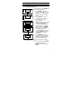
2. Getting Acquainted 2.1 Front Panel The front panel consists of a 3 digit LED display together with 5 LED annunciators. There are also 4 keys as shown below. 888 pH/ OR o C SETUP REA DY MODE ENTER RELA Y The keys available are the ▲ (UP/INCREMENT), ▼ (DOWN/DECREMENT), MODE and ENTER keys. The annunciators are pH/ORP, °C, SETUP, READY, and RELAY. The function of the annunciator is to provide additional information, for example, the pH/ORP annunciator lights up in pH/ORP measurement mode.
2.2 Back Panel The back panel consists of two connectors. The first one is a 4way screw terminal and the second is a 12-way screw terminal. Refer to the label on top of the unit for diagram. The connection for the 4-way screw terminals are (from the left to right): 1. PT 100 connection 2. PT 100 connection 3. No connection 4. No connection The connections for the 12-way screw terminals are (from left to right), 5. Low Set Relay deactivated position 6. Low Set Relay center pole 7.
2.3 Selecting pH/ORP Measurement Mode You can set the appropriate pH/ORP measurement mode from the jumper. See Appendix 1 for details on the jumper positions for pH mode and Appendix 2 for jumper positions for ORP mode. 2.4 Wiring Connect the power supply to the GND (EARTH) - 13 or 14, NEUTRAL - 15 and LIVE - 16 screw terminals. Make sure that the power supply jumper setting matches the mains voltage (110 VAC or 220 VAC). See Appendix 2 for the jumper setting for the voltage selection.
3. Operating the Controller 3.1 The Main Display Press MODE key to switch to three main displays - the pH/ORP display, the temperature display and “SEt” display. Press MODE key once to get into the temperature measurement. The °C annunciator lights up when you are measuring temperature. The display shows current measured temperature (with ATC) or the temperature that was set in MTC mode. Press MODE key again and the display toggles to the “SEt” for SETUP menu. 7.4 MODE ENTER pH/ORP 24.
4. Setting Up the Controller 4.1 Setting and Changing the Password 4.1.1 Setting New Password To set a password, press MODE key until the “SEt” is displayed. ENTER 1. Press ENTER key and the SETUP display shows "CAL” and “PH” alternately. Press ▲ key once and the display shows “SEt” MODE “id”. ENTER 2. Press ENTER to enter your desired password. Follow the SETUP steps below (e.g. using a password “123”). MODE 1. Initially, the display shows "000" with the first digit blinking. ENTER SETUP 2.
To calibrate the controller at any time, you may have to enter the password that you set, in order to access the calibration mode. Once you have entered the password correctly, the display shows "CAL PH” indicating that you are in one of the lower-level SETUP menus. If you enter the wrong password, the display reverts back to the pH display. Alternatively, if you prefer no password protection, set the password to “000”, "CAL PH" immediately displays after you press ENTER key while you are in the "SEt" menu.
5. Calibrating the Controller 5.1 The Lower Level Menus The "CAL PH/CAL OrP" display is the first menu seen upon entering the lower-level menus, depending on which mode is set. Press ▲ or ▼ key to display the various menus as shown in the figure below. Press ENTER key to go to the lower level menus. START CAL pH / CAL OrP o CAL C Lo Hys SEt id Hi SEt Hi Hys Lo SEt 5.2 Calibrating for pH Measurement 5.2.1 The CAL PH menu 1.
complete the pH calibration, as fo pH 7.0. Press MODE key to return to measurement mode. Note : If the pH value is not near MODE to any buffer, pressing ENTER will not calibrate the controller. If at ENTER any point, you decide not to SETUP calibrate, you can return to the previous mode by pressing the MODE key. CAL PH MODE ENTER 5.3 Changing the Offset SETUP If the controller calibration has drifted, you can reset the offset of controller. First, go to the calibration mode.
5.4 Calibrating for ORP Measurement 1. 2. 3. Make sure that the ORP mode is MODE set before calibration. ENTER Enter this menu by pressing SETUP MODE key twice to the “SEt” display if you are in measurement mode. Press ENTER key. If the password MODE has been set earlier, key in the ENTER password using the method SETUP described in section 4.1. Press ENTER once to confirm. After you set the correct password, you can see the “CAL” and “OrP” displays MODE blink alternately.
2. the “CAL” and “PH” display blinks alternatively. Press ▼ key once, the display shows “CAL”“oC” blinking. Press ENTER and the display alternatively shows “Atc” and “On” or “Atc” and “OFF”. Use ▲ and ▼ keys to choose between both ATC ON and ATC OFF. 5.5.2 ATC ON/OFF Atc MODE ENTER SETUP On MODE ENTER SETUP 23.5 SETUP 13 MODE ENTER ATC ON : If a PT 100 is connected, use ▲ and ▼ keys to adjust the temperature offset of the PT 100 by ± 5 °C. Dip the temperature probe into the sample liquid.
Atc MODE ENTER SETUP OFF MODE ENTER SETUP 25.0 SETUP MODE ENTER ATC OFF : If a PT 100 is not used, then the ATC should be set to OFF. In step 3 above, choose by pressing ▲ and ▼ keys to select ATC OFF. Then press ENTER. The display will now show the default of 25 oC or the last set value (blinking). Use ▲ and ▼ keys to set your desired value. Press ENTER to confirm and the display shows “CAL” “Con”. Note : For ATC OFF, you can adjust the set temperature values from 0.0 to 99.9 oC.
5.6 Setting the Alarm Feature This menu allows you to change the High and Low Setpoint and Hysteresis values. See Section 8 for hysteresis applications. IMPORTANT : When SETUP mode is entered, the 4-20 mA output (only for transmitter CX model) freezes and the relay deactivates (if it was in an alarm condition). 5.6.1 The Hi SET Menu MODE 1. Enter this menu by pressing ENTER MODE key twice to the “SEt” SETUP display if you are in measurement mode. 2. Press ENTER key.
5.6.2 The Hi HYS Menu 1. HYS MODE ENTER SETUP Hi 2. MODE ENTER SETUP 0.2 MODE ENTER 1. SETUP NOTE : The maximum value of Hysteresis is 0.2 pH to 2.0 pH or 20 mV to 200 mV. The HI HYS hysteresis is spread equally on either side of the Hi SET point. 2. 3. Enter this menu by pressing the MODE key to the “SEt” display if you are in the measurement mode. Press ENTER key. If the password has been set earlier, key in the password using the method described in section 4.1.
5.6.3 The Lo SEt Menu 1. 2. 3. 1. 2. 3. 17 Enter this menu by pressing MODE key twice to the “SEt” display if you are in measurement mode. Press ENTER key. If the password has been set earlier, key in the password using the method described in section 4.1. Press ENTER once to confirm. After you set the correct password, you see the “CAL” and “PH” display blinks alternately. Press ▼ key four times, the display shows “Lo” “SEt” blinking alternately.
5.6.4 The Lo HYS Menu 1. HYS MODE ENTER SETUP 2. Lo MODE ENTER 3. SETUP 0.2 MODE ENTER SETUP 1. NOTE : The maximum value of Hysteresis is 0.2 pH to 2.0 pH or 20 mV to 200 mV. The Lo HYS hysteresis is spread equally on either side of the Lo SET point. 2. Enter this menu by pressing the MODE key to the “SEt” display if you are in the measurement mode. Press ENTER key. If the password has been set earlier, key in the password using the method described in section 4.1.
6. Using the Controller Current Loop for Datalogging (for Transmitter Model Only) The 4-20 mA Current Loop A 4-20 mA current loop can be connected if a remote data logging is required. The current will be proportional to the pH/ORP displayed on the panel display. The 4-20 mA current loop can drive a load resistance of no more than 200Ω. If the pH is less than 0.0 pH, the current signal will be set to approximately 0 mA. If the pH is greater than 14.0 pH, it will be set to approximately 21 mA.
7. Additional Information The controller allows you to set High and Low alarms that switch on or off relays, and activating or deactivating devices linked to the controller. In cases where the pH/ORP values fluctuate close to the high or low setpoints, the relays will continuously switch on/off very quickly and may cause problems to the linked devices. The hysteresis band allows you to set an allowable range of fluctuations to prevent the relays from activating and deactivating too quickly. See below.
Explanation of the diagram in the previous page A - Reading reaches (Hi SET - ½ HI HYS), the Hi-Set relay remains inactivated. B - Reading reaches above High Setpoint but below (Hi SET + ½ Hi HYS), Hi-Set relay remains inactivated. C - Reading reaches between (Hi SET - ½ Hi HYS), the Hi-Set relay remains inactivated. D - Reading reaches above (Hi SET + ½ Hi HYS), and the HiSet relay is activated. E - The Hi-Set relay is inactivated only when the reading falls below (Hi SET - ½ Hi HYS).
JP1 Selects the input voltage between 110 VAC or 220 VAC JP3 & JP4 Selects for pH or ORP mode. Please refer to Appendix 2A and 2B for the diagrams JP2 OPEN (DEFAULT) SHORT Terminals 5 & 6, 8&9 6 & 7, 9 & 10 5 & 6, 8&9 6 & 7, 9 & 10 Power On OPEN CLOSE CLOSE OPEN pH within setting OPEN CLOSE CLOSE OPEN pH exceeding setting CLOSE OPEN OPEN CLOSE Fuse Note that there is a fuse internal to the controller.
Appendix 2A - Jumper Positions, pH Jumper Positions - inside the Controller 23
Appendix 2B - Jumper Positions, ORP Jumper Positions - inside the Controller 24
Appendix 3 - pH Offset / Slope mV Axis Current pH curve 7.5 pH Axis 4.0 4.5 Adjusted pH curve 25 7.0 10.0 10.
8. Technical Specifications pH Range Resolution Relative Accuracy mV Range Resolution Relative Accuracy Temperature Compensation Temperature Resolution Relative Accuracy Sensor Calibration Calibration Options Output Display Inputs Input Impedance Input Bias Current Recommended Input Cable Length Relays No. Of Relays Maximum Voltage Maximum Current High Hys. Band Low Hys. Band Power Requirements Environmental Requirements Operating Storage Humidity Limits Storage Temp. Range Dimensions 0.0 to 14.0 pH 0.
NOTES 27