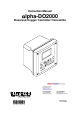
Instruction Manual αlpha-DO2000 Dissolved Oxygen Controller/Transmitter Technology Made Easy ...
Preface This manual serves to explain the use of the αlpha DO 2000 Series. The manual functions in two ways, firstly as a step by step guide to help the user operate the instrument, and secondly as a handy reference guide. This instruction manual is written to cover as many anticipated applications of the αlpha DO 2000 as possible. If you have any doubts concerning the use of the instrument, please do not hesitate to contact the nearest Eutech Instruments Authorised Distributor.
Safety Information This Controller/ Transmitter shall be installed and operated only in the manner specified in the Instruction manual. Only skilled, trained or authorised person should carry out installation, setup and operation of the instrument. Before powering up the unit, make sure that power source it is connected to, is as specified in the top label. Failure to do so may result in a permanent damage to the unit. The unit has live and exposed parts inside.
TABLE OF CONTENTS 1 INTRODUCTION ....................................................................................................................................... 1 1.1 1.2 1.3 1.4 2 AT THE VERY BEGINNING ...................................................................................................................... 1 INTENDED USE ...................................................................................................................................... 1 SAFETY INTSRUCTIONS .......
8.11 8.12 9 ACCESSORIES......................................................................................................................................... 35 9.1 9.2 10 REPLACEMENT UNIT ........................................................................................................................... 35 ASSEMBLY ACCESSORIES ................................................................................................................... 35 GENERAL INFORMATION..............................
αlpha DO 2000 Instruction manual 1 INTRODUCTION 1.1 At the very beginning We thank you for having purchased the αlpha DO 2000. The construction of the αlpha DO 2000 employs leading edge technology and complies with safety regulations currently in force. Notwithstanding this, improper use could lead to hazards for the user or a third-party, and/or adverse effects on the plant or other equipment.
αlpha DO 2000 Instruction manual 1.3 Safety intsructions The αlpha DO 2000 should be installed and operated only by personnel familiar with the transmitter and who are qualified for such work. A defective transmitter must neither be installed nor put into service. The αlpha DO 2000 must only be operated under the specified operating conditions The αlpha DO 2000 must not be repaired by the customer.
αlpha DO 2000 Instruction manual 2 PRODUCT DESCRIPTION 2.1 Description of unit The αlpha DO 2000W is used for measuring dissolved oxygen and temperature values. The dissolved oxygen values can be measured using industrial dissolved oxygen sensors. The temperature values can be measured using 2-wire / 3-wire Pt100 /Pt1000 sensors.
αlpha DO 2000 Instruction manual 2.2 Measurement and control system A typical measurement system consists of: • A dissolved oxygen process transmitter • A dissolved oxygen sensor with integrated or separate temperature sensor Pt100/Pt1000.
αlpha DO 2000 Instruction manual 2.
αlpha DO 2000 Instruction manual 2.3.1 Display Overview The LC display shows two alpha-numerical fields for parameters and measured values as well as various mode and status indicators. Mode indicators: SETUP MEAS CAL HOLD ERR 13.0 MEAS: measurement mode % SETUP: Set-up mode ppm CAL: Calibration mode mg/l Status indicator: °C °F HOLD: Unit in “HOLD” mode ATC: Visible in ATC (Automatic Temperature Compensation) mode. Not visible in the Manual Temperature Compensation mode.
αlpha DO 2000 Instruction manual 2.3.3 LED indicators Relay indicators If REL key is pressed the LED (A, B or W) indicates to which Relay (A, B or Wash) the displayed limit values refer. Relay mode indicators Auto LED lights if relay operation is set to automatic mode. Manu LED lights if relay operation is set to manual mode. Relay status indicators This LED lights if limit value is exceeded or the ATC probe fails.
αlpha DO 2000 Instruction manual 2.3.5 Menu overview MEAS 13.0 % °C 4 CAL ENTER ENT 1 2 1 ENTER ENT CCD “000” = Check calibration parameters (View only mode) CCD “11” = Calibration mode SCD “000” = Check setup parameters (View only mode) SCD “22” = Setup mode 2 ENTER ENT SETUP HOLD OFS ENT Pressure Compensation settings see section 6.2 SETUP HOLD SETUP HOLD SETUP HOLD SETUP ENT ENT ENT ENT HOLD SETUP HOLD SETUP HOLD SETUP HOLD Relay B (set point 2) settings see section 6.
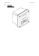
αlpha DO 2000 Instruction manual 3 ASSEMBLY AND INSTALLATION 3.1 Mounting the unit Wall mounting version 111.50 [4.39] 144 [5.67] ] 7 6 5 [ 4 4 1 27.5 [1.08] . ] 5 5 [ 4 1 xo p p a . . r For Pg13.5 cable glands 24 [.94] 39 [1.54] Pg13.5 (3 pcs.) 78 [3.07] 57.8[2.28] 80 [3.15] ]2 6 2 [ 5 6 6 ]5 8 [ 5 1 2 Holes for post mounting (4X) . . . Holes for wall mounting (2X) . ] 4 5 3 [ 0 9 6 [.24] . Unit: MM [INCH] 90 [3.
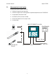
αlpha DO 2000 Instruction manual 3.2 Connection Diagram Caution: Ensure electrical mains are disconnected before proceeding.
αlpha DO 2000 Instruction manual NOTE: a) Switch or circuit breaker shall be included in the building installation. b) It shall be in close proximity to the equipment and within easy reach of the operator. c) It shall be marked as the disconnecting device for the equipment.
αlpha DO 2000 Instruction manual 4 NORMAL OPERATION 4.1 Measurement mode When the controller/transmitter is powered on, the display first shows all segments briefly, after which the controller/transmitter automatically enters into the Measurement mode. Please note: To guarantee accurate readings the measuring system (transmitter and sensor) must be calibrated. MEAS % 13.0 °C ATC The mode indicator “MEAS” at the top of the display indicates that the transmitter is in Measurement mode.
αlpha DO 2000 Instruction manual 5 CALIBRATION MODE You can access the Calibration mode directly from the Measurement mode by pressing the CAL key and entering the Calibration security code “11”. Calibration mode may also be accessed via the Setup mode (see section 6.1). 5.1 Entering Calibration mode MEAS 13.0 % °C 4 CAL 11 ENT ENTER ENT 22 ENT SETUP HOLD SETUP HOLD OFS CAL DO Pressure Compensation Setting ENT 1-point or 2-point Calibration See section 5.2 1.
αlpha DO 2000 Instruction manual 5.2 Dissolved oxygen Calibration in mg/l or ppm of oxygen If the unit of measure is in mg/l (default) or ppm, then the calibration is also carried out in mg/l or ppm. This transmitter features a one-point or two-point calibration for dissolved oxygen. Displayed value should be within +/- 50 % of high point SETUP HO LD CAL ENT SETUP HO LD DO 1-PT ENT CAL READY HO LD HI HO LD mg/l 8.24 CAL CAL ENT 1.00 24.5 ENT ENT o C CAL MEAS 8.24 24.
αlpha DO 2000 Instruction manual displayed value to the correct value. Press the ENT key to accept the value and the status of the probe is displayed. Note: If the displayed value is not within ±50% of the high point value, the controller will not accept the high-level calibration and retains the previous calibration values.
αlpha DO 2000 Instruction manual Note: If there is a calibration error, the controller displays “CAL ERR” and exits to the measurement mode (for direct access calibration mode) or to the setup menu (for calibration mode accessed via Setup mode). 5. For Two-Point Calibration, calibration is carried out at 0% saturation first. Immerse the probe in zero oxygen solution and allow it to stabilize. The “CAL” indicator flashes at the top. When the reading is stable, the “READY” annunciator comes on.
αlpha DO 2000 Instruction manual 6 SETUP MODE 6.1 Enter Setup mode In the Setup mode the transmitter can be configured to your individual requirements. 1. While in Measurement mode press the ENT key. 2. The display prompts you to enter the security code. Set the security code with ▲ or ▼ key to: − “SCD 22” if you want to change parameter settings − “SCD 000” if you want to view only parameter settings (view only mode) 3. Press the ENT key ME AS 13.
αlpha DO 2000 Instruction manual 6.2 Offset, Salinity and Pressure compensation (OFS) sub-function This mode allows you to change the offset parameter to make reading corrections without removing the electrode from the control system. You can make adjustments of up to ±2.00ppm; ±2.00 mg/l; or ±10.0%. At the end of the offset adjustment, the salinity value, followed by the pressure values (in mmHg or Pascal or PSI) respectively, is entered. SETUP SETUP OFS HOLD HOLD 0.03 ENT SETUP HOLD mg/l 0.
αlpha DO 2000 Instruction manual 6.3 Setting temperature (Set °C°F) sub-function SETUP HOLD ENT SETUP ENT HOLD SETUP ENT HOLD SETUP ENT HOLD SETUP ENT HOLD °C ATC SETUP SETUP HOLD HOLD ENT SETUP ATC ENT HOLD °F °C ATC 1. Select the “SET °C°F” sub-function, then press the ENT key. 2. Selecting temperature unit: press the ▲ or ▼ key to select the desired temperature unit “°C” or “°F”. Press the ENTER key to confirm your selection. 3.
αlpha DO 2000 Instruction manual 6.4 Control Relay A / Relay B (SP1/SP2) sub-function The SP1 sub-function determines the operating parameters for Relay A; while SP2 defines the operating parameters for Relay B. Since these groups have the same set-up parameters, they are described together. SETUP HOLD ENT SETUP HOLD 90.0 % ENT SETUP ENT HOLD SETUP HOLD 2.0 % ENT SETUP HOLD ENT SETUP HOLD SETUP HOLD 1. Select the “SP1” (Relay A) or “SP2” (Relay B) sub-function, then press the ENT key. 2.
αlpha DO 2000 Instruction manual 5. Setting the on-delay time lag: press the ▲ or ▼ key to enter the on-delay time for set point 1 (set point 2). The controller will delay activation of the relay for the number of seconds (0 to 2000 seconds) you select. Press the ENT key to confirm your setting. Note: You can set a time delay for each relay, which stops the relay from switching on the moment the set point is exceeded. This controller lets you set a 0 to 2000 seconds time delay before your relay activates.
αlpha DO 2000 Instruction manual 6.5 Controller (CNTR) sub-function The CNTR sub-function determines the controller’s parameters.
αlpha DO 2000 Instruction manual 1. Select the “CNTR” subfunction, then press the ENT key. 2. Selecting the controller type: press the ▲ or ▼ key to select the suitable controller type: − OFF = controller off Use control Off to operate controller as a monitor only or to prevent relays from switching. − L.CT = limit value control (on/off control).
αlpha DO 2000 Instruction manual − If the proportional controller type is set to pulse frequency control (PFC): 9. Selecting the relay status under Non-Alarm condition: press the ▲ or ▼ key to choose the desired relay status (de-energized = “DEEN” or energized = “EN”). Press the ENT key to confirm your selection. 10. Setting the proportional range: press the ▲ or ▼ key to set the proportional range (setting range: 10 to 500%). Press the ENT key to confirm your setting. 11.
αlpha DO 2000 Instruction manual 6.6 Current Output 1 sub-function In this subfunction you set the current output range of the transmitter for dissolved oxygen values. SETUP HOLD ENT SETUP HOLD ENT SETUP % HOLD ENT SETUP HOLD 90.0 % ENT SETUP HOLD ENT ENT SETUP HOLD SETUP ENT % HOLD ENT SETUP HOLD 90.0 % SETUP HOLD 1. Select the “CUR.1” subfunction, then press the ENT key. 2. Selecting the output type: press the ▲ or ▼ key to select the desired output type: 0-20 mA or 4-20 mA.
αlpha DO 2000 Instruction manual 6.7 Current Output 2 sub-function In this sub-function you set the current output range of the transmitter for temperature values. SETUP HOLD ENT SETUP HOLD SETUP SETUP ENT ENT HOLD °C SETUP HOLD SETUP ENT °C ENT HOLD °C ENT HOLD SETUP ENT HOLD °C 1. Select the “CUR.2” sub-function, then press the ENT key. 2. Selecting the output type: press the ▲ or ▼ key to select the desired output type: 0-20 mA or 4-20 mA.
αlpha DO 2000 Instruction manual 6.8 Wash relay (WASH) sub-function In this sub-function you set the parameters for the wash relay. SETUP HO LD ENT SETUP HO LD ENT SETUP ENT HO LD SETUP HO LD ENT SETUP HO LD ENT ENT SETUP SETUP HO LD HO LD 1. Select the “WASH” sub-function, then press the ENT key. 2. Enabling/disabling wash function: press the ▲ or ▼ key to enable (WASH ON) or disable (WASH OFF) wash function. Press the ENT key to confirm your selection. 3.
αlpha DO 2000 Instruction manual 6.9 Configuration (CNFG) sub-function In this sub-function you configure the transmitter to suit your requirements. SETUP HOLD ENT SETUP ENT HOLD SETUP ENT HOLD SETUP HOLD ENT UNIT SETUP HOLD mg/l do ENT SETUP SETUP ENT HOLD HOLD UNIT ppm do SETUP HOLD UNIT % do SETUP ENT HOLD SETUP HOLD 0-40 ENT SETUP ENT HOLD EL ENT ENT SETUP SETUP HOLD HOLD MEAS SETUP 0-10 HOLD EL CAL ENT 31.0 % °C ATC SETUP HOLD FCT ENT 1.
αlpha DO 2000 Instruction manual 6. Selecting the alarm contact type: press the ▲ or ▼ key to select the alarm contact type: − “STDY” = steady contact − “FLET” = fleeting (single pulse) contact Press the ENT key to confirm your selection. Note: With this parameter you select whether the alarm contact will operate as a steady contact or a fleeting (single pulse) contact. Pulse contact closing time is 1 second. 7.
αlpha DO 2000 Instruction manual 7 RELAY MODES You can control devices connected to Relay A, Relay B or wash relay via the front panel of the transmitter. In Automatic mode, the transmitter’s set point values activate the relays. In Manual mode, you can manually turn “on” and “off” the control devices connected to the relays. 7.1 View relay set points To view relay set points, the relay mode must be set to automatic (standard mode after switchon, relay mode LED “Auto” lights).
αlpha DO 2000 Instruction manual 7.2 Manual relay mode In manual relay mode, you can manually turn “on” and “off” the control devices connected to Relay A, Relay B or Wash relay. 1. While in Measurement mode press the MODE key. 2. The display prompts you to enter the security code. Press the ▲ or ▼ key to set security code to “22”. 3. Press the ENT key. The Manual relay mode is activated and the relay mode LED “Manu” lights.
αlpha DO 2000 Instruction manual 8 TECHNICAL SPECIFICATIONS 8.1 Measurement and Compensation (a) Dissolved Oxygen Dissolved Oxygen Measuring Range Resolution Relative accuracy (b) Temperature Temperature measuring range Resolution Relative accuracy Sensor (c) Compensation Temperature Compensation Pressure Compensation Salinity Compensation 8.2 0.00 to 25.00 mg/l or 0.00 to 25.00ppm or 00.0 to 300.0 % Saturation 0.01 mg/l or 0.01 ppm or 0.1 % 1.5 % of full-scale reading for all ranges -10.0 to +125.
αlpha DO 2000 Instruction manual (c) P/PI Control only Proportional Range Integral Action Time (IAT) (c) (1) Pulse Length Control (PLC) Pulse Length (c) (2) Pulse Frequency Control (PFC) Pulse Frequency Contact Outputs Switching Voltage / Current / Power 8.3 Wash Cycle Interval Wash Duration Contact Outputs Switching Voltage / Current / Power 60 to 120 pulses / minutes Two SPST relays Max 250VAC / Max 3A / Max 600VA Energise (EN) or De-energise (DEEN) 0.1 to 200.
αlpha DO 2000 Instruction manual 8.6 Voltage Output & Hold Function Switch +12 V Output Hold Function Switch 8.7 Display LCD Back light 8.8 5-pin, 8-pin, 9-pin & 13-pin terminal connectors 144 x 144 x 111.5 mm 950g (unit) / 1100g (Packed) NEMA 4X, IP65 Electromagnetic Compliance (EMC) Specifications Emitted Interference Immunity to Interference 8.12 8-pin Screw Terminal (3.5mm pitch) 8-pin Screw Terminal (3.5mm pitch) 9-pin Screw Terminal (7.62mm pitch) 13-pin Screw Terminal (3.
αlpha DO 2000 Instruction manual 9 ACCESSORIES 9.1 Replacement Unit Product Description Eutech Instruments Order Code αlpha DO 2000 Controller / Transmitter, wall mount version 9.2 EC-DOCTP2000W Assembly Accessories Eutech Instruments Order Code Product Description General Purpose Dissolved Oxygen Probe ECDOGEN 0.
αlpha DO 2000 Instruction manual 10 GENERAL INFORMATION 10.1 Warranty Eutech Instruments warrants this product to be free from significant deviations in material and workmanship for a period of one year from the date of purchase. If repair is necessary and not the result of abuse or misuse within the warranty period, please return by freight pre-paid and amendment will be made without any charge. Eutech Instrument Customer Service Dept.
αlpha DO 2000 Instruction manual 11 APPENDICES 11.1 Appendix 1 – Unit fuse and jumper settings Caution! Before opening the unit to replace the unit fuse or to set the jumper for Pt 100 / Pt 1000 temperature sensor, make sure the mains cable is separated from the power supply.
αlpha DO 2000 Instruction manual 11.2 Appendix 2 – Salinity vs Temperature (@ 760 mmHg) The following table shows the Dissolved Oxygen values at different salinity values, at different temperatures, at barometric pressure of 760 mmHg. For other pressure levels, the controller automatically corrects the value based on the pressure value input. Temperature o C F 0 32.0 1 33.8 2 35.6 3 37.4 4 39.2 5 41.0 6 42.8 7 44.6 8 46.4 9 48.2 10 50.0 11 51.8 12 53.6 13 55.4 14 57.2 15 59.0 16 60.8 17 62.6 18 64.
αlpha DO 2000 Instruction manual 11.3 Appendix 3 – Simple explanation on the function of hysteresis SP1 Set to LO SP2 Set to HI RELAY ON RELAY OFF 10 12 88 SP1 90 % SP2 FORWARD DIRECTION HYSTERESIS BAND REVERSE DIRECTION The controller relay activates when the set-point is reached. In the reverse direction, it does not de-activate when the value reaches the set-point. Instead, it continues to be active till the value reaches the amount set by the Hysteresis band.
αlpha DO 2000 Instruction manual 11.4 Appendix 4 – General instructions concerning Controller Setting 11.4.1 Control characteristic of Controllers used as limit value switch MIN function 100% MAX function Yh 50% 0% -Xw 11.4.2 +Xw SP 1 SP 2 Xp = 0 Xp = 0 Control characteristic of P-Controllers as proportional controller MIN function 100% MAX function Yh 50% 0% -Xw +Xw Xp Xp Prop. band Prop. band SP 2 SP 1 11.4.
αlpha DO 2000 Instruction manual 11.4.4 Control signal of Pulse length Controllers Relay Pulse Length T tON tOFF ON OFF Time [s] The output relay of the pulse length controller is clock-timed. The switching period T remains constant. Depending on the divergence from the limit value, the switch on time tON is increased or decreased in accordance with the proportional range Xp. The following applies: tON + tOFF = T (Const.
αlpha DO 2000 Instruction manual 11.4.5 Control signal of Pulse Frequency Controllers Relay Pulse Length T tON tOFF ON OFF Time [s] The output relay of the pulse frequency controller is clock-timed. The pulse duration tON remains constant at 250 msec. Depending on the divergence from the limit value, the frequency (1/T) is increased or decreased in accordance with the proportional range Xp. The following applies: tON = Const. (250 msec.
αlpha DO 2000 Instruction manual 11.5 Appendix 5 – Abbreviations used in menu displays Abbreviation Meaning Abbreviation Meaning MEAS Measurement F. PF Pulse frequency CAL Calibration IAT Integral action time ENT Enter MANU Manual C. CD Calibration security code CUR. 1 Output current 1 S. CD Setup security code CUR.
For more information on the products, contact your nearest distributor or visit our website listed below: Eutech Instruments Pte Ltd. Blk 55, Ayer Rajah Crescent, #04-16/24 Singapore 139949 Tel: (65) 6778 6876 Fax: (65) 6773 0836 E-mail: marketing@eutechinst.com Web-site: www.eutechinst.