
User Guide

Operating Manual alpha DO 1000
4
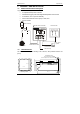
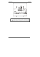
3.2 Back Panel
The back panel consists of two connectors. The first connector is the 17-way PCB
edge connector and the other is the 5-way connector.
ENSURE that the power cable is physically separated from the power
supply.
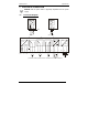
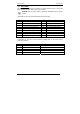
Connection for the 17-way screw terminals (from left to right):
Pin No Description Pin No Description
1 AC mains live wire 10 Alarm relay resting position (NO)
2 AC mains neutral wire 11 Alarm relay common
3 AC mains protective earth wire 12 Alarm relay working position (NC)
4 Low set relay resting position (NC) 13 Hold function switch terminal 1
5 Low set relay common 14 Hold function switch terminal 2
6 Low set relay working position (NO) 15 No connection
7 High set relay resting position (NC) 16 0/4 - 20 mA for -ve connection
8 High set relay common 17 0/4 - 20 mA for +ve connection
9 High set relay working position (NO)
Connections for the 5-way screw terminals (please refer to DO probe wiring
instruction manual):
Pin No Description DO Probe Wiring Colour
18 Pt100 lead 1 White
19 Pt100 sense lead Red
20 Pt100 lead 2 Black
21 Cathode, –ve connection Green
22 Anode, +ve connection Yellow