Instruction Manual αlpha-DO 1000 Dissolved Oxygen Controller/Transmitter Technology Made Easy ...
Preface This manual serves to explain the use of the αlpha-DO1000 series Dissolved Oxygen controller/transmitter. The manual functions in two ways: firstly as a stepby-step guide to help the user operate the instrument. Secondly, it serves as a handy reference guide. This instruction manual is written to cover as many anticipated applications of the αlpha-DO1000 Dissolved Oxygen controller/transmitter.
Operating Manual alpha DO 1000 Safety Information The Eutech Controller/ Transmitter shall be installed and operated only in the manner specified in the Instruction manual. Only skilled, trained or authorized person should carry out installation, setup and operation of the instrument. Before powering up the unit, make sure that power source it is connected to, is as specified in the top label. Failure to do so may result in a permanent damage to the unit. The unit has live and exposed parts inside.
Operating Manual alpha DO 1000 TABLE OF CONTENTS 1 INTRODUCTION ..................................................................................... 1 1.1 1.2 2 Description of Unit................................................................................................................1 Applications...........................................................................................................................1 ASSEMBLY AND INSTALLATION ................................................
Operating Manual 7.7 7.8 7.9 8 alpha DO 1000 7.6.1 Entering the Controller sub-function .....................................................................22 7.6.2 Choosing the controller type (limit or proportional).............................................22 7.6.3 Choosing Break/Make Contact Relay Type ...........................................................23 7.6.4 Selecting Proportional Range Value, Xp ...............................................................23 7.6.
1 1.1 INTRODUCTION Description of Unit Thank you for purchasing Eutech’s ¼ DIN alpha-1000 series Dissolved Oxygen process controller. This unit is used for measuring either in % saturation, mg/l or ppm, one at a time, and the operational mode is switchable from the menu. You can use this unit to measure Dissolved Oxygen with limit or proportional control.
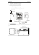
Operating Manual 2 alpha DO 1000 ASSEMBLY AND INSTALLATION 2.1 Measurement and Control System A typical measurement system consists of: • an αlpha-DO1000 process controller • a Dissolved Oxygen probe with integrated temperature sensor Pt100 • an immersion, flow or process assembly • a final control element such as pump or valve, and • a chart recorder Flow Assembly lpha-DO 1000 Controller Chart Recorder lpha-DO 1000 Alarm / Siren System Measurement Cable DO Electrode 2.
Operating Manual 3 alpha DO 1000 ELECTRICAL CONNECTION ENSURE that the power cable is physically separated from the power supply. 3.
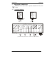
Operating Manual 3.2 alpha DO 1000 Back Panel The back panel consists of two connectors. The first connector is the 17-way PCB edge connector and the other is the 5-way connector. ENSURE that the power cable is physically separated from the power supply.
Operating Manual alpha DO 1000 DO Probe Pt100 FUSE 250VAC 100mA (F) J2 RELAY2 ALARM HOLD NC - N + RELAY1 L PE IMPORTANT: The Alarm relay functions as an “Active Low” device i.e. it switches OFF under Alarm condition. Therefore the Alarm display device should be connected to the ‘NC’ contacts of the relay.
Operating Manual 4 alpha DO 1000 OVERVIEW 4.1 Keypad and Display 4.1.1 Keypad 4.1.2 • Perform rapid calibration • Allows entry to Set up mode • Select individual functions within the function group of Set up mode • Store input data in the Set up mode • Start calibration in the calibration mode • Select various function groups in the Set up mode.
Operating Manual 4.2 alpha DO 1000 Function Groups The main function and sub-function groups are organised in a matrix format for configuration and selection of parameters. The main function groups are: Offset adjustment (OFS). See Section 7.1. Temperature Measurement / compensation settings (SEt °C). See Section 7.4. Control relay 1 configuration (SP1). See Section 7.5. Control relay 2 configuration (SP2). See Section 7.5. Control type (Cntr). See Section 7.6.
Operating Manual 4.3 alpha DO 1000 Control Concept The main function and sub-function groups are organised in a matrix format as shown below. These functions can be accessed via the front keypad for configuration and selection of parameters. MEASURE CODE OFFSET Set Offset SET C Set Salinity Set Pressure Switch On / Off ATC Process temp. (MTC) Calib. temp.
Operating Manual 5 5.1 alpha DO 1000 MEASUREMENT Display in Measurement mode When the controller is initially powered on, it automatically enters into the Measurement mode after the large dual LCD displays all segments briefly. The upper display shows the measured Dissolved Oxygen value, while the lower display shows the temperature value. Annunciators at the right side of the display indicate measurement units: ppm, mg/l or % measurement.
Operating Manual 5.2 alpha DO 1000 Security Codes This controller has two levels of security protection with separate security codes. The first level allows entry into the Calibration mode: security code = 11; the second allows entry into the SETUP mode: security code = 22. The security codes protect the controller from unauthorised tampering of its current setting. The parameters cannot be changed unless the security code is entered. 5.2.1 1.
Operating Manual alpha DO 1000 NOTE: If you want to view (not change) set up parameters, push the ENTER key when the security code reads “000”. 5.2.4 Clearing the Advanced Setup Security Code from the Display After you have entered the security code and returned to the Measurement mode, the security code “22” still appears on the display whenever you press the ENTER key. To conceal the security code, you must manually reset the code. To clear the Advanced Setup security code from the display: 1. 2.
Operating Manual 6 alpha DO 1000 CALIBRATION MODE You can reach the Calibration mode directly from the Measurement mode by pressing the CAL key and entering the Calibration security code. You can also reach the Calibration mode from the Advanced Setup mode. 6.1 HOLD SETUP Cal Dissolved Oxygen Calibration If the units of measure is in mg/l (default), then the calibration is also carried out in mg/l. The Dissolved Oxygen Controller allows a one- or two-point calibration. 1. 2. 3. 4.
Operating Manual 5. alpha DO 1000 If the calibration is successful, the controller switches to the second point, which is the high-level of dissolved oxygen. Take the probe out of the solution and immerse it in a solution with a higher concentration of dissolved oxygen. When the reading is stable, “READY” annunciator comes on. Use the ▲ or ▼ keys to adjust the displayed value to the correct value. Press ENTER key to accept the value and the status of the probe is displayed.
Operating Manual 4. alpha DO 1000 annunciator comes on. Press ENTER key to accept the value and the controller displays the status of the probe. For Two-Point Calibration, calibration is carried out at 0% saturation first. Immerse the probe in solution and allow it to stabilise. When the reading is stable, the “READY” annunciator comes on. Press the ENTER key to accept the value.
Operating Manual 7 alpha DO 1000 ADVANCED SET-UP MODE 7.1 Electrode Offest (OFS), Salinity and Pressure sub-function This mode allows you to change the offset parameter to make reading corrections without removing the electrode from the control system. You can make adjustments of up to ±2.00ppm; ±2.00 mg/l; or ±10.0%. At the end of the offset adjustment, the salinity value, followed by the pressure values (in mmHg or Pascal) respectively, is entered. HOLD SETUP HOLD ofs SETUP HOLD 0.02 0.
Operating Manual alpha DO 1000 pressed to adjust the Dissolved Oxygen value, you will see that the ‘offset’ value in its upper display also changes. 9. Press the ENTER key to accept the offset value. Note: The offset value is reset during full calibration (See section 6). 10. Proceed to input Salinity values or return to Measurement mode by pressing the ▲ and ▼ keys (escape) simultaneously. 7.2 Setting the Salinity Value 1. 2. 3. 4. 5. 6. 7.3 Enter Advanced set-up mode.
Operating Manual 6. 7. 7.4 alpha DO 1000 Press the ENTER key to accept the correct pressure values. The controller automatically compensates the final Dissolved Oxygen measurement. Proceed with additional Advanced Set-up procedures (press ENTER again) or return to Measurement mode by pressing the ▲ or ▼ keys (escape) simultaneously. Setting Temperature (Set °C) sub-function 7.4.1 1. 2. 3. 4. 5. 7.4.2 1. 2. 3. 4. Selecting Automatic or Manual Temperature Compensation Enter Advanced Set-up mode.
Operating Manual 7.4.3 alpha DO 1000 Setting Manual Temperature Compensation Note: This parameter is blanked out when the controller is set for ATC operation. For manual temperature compensation, you can set two different temperatures: process and calibration. This allows calibration at a temperature other than your process temperature.
Operating Manual 7.5.1 1. 2. 7.5.2 alpha DO 1000 Entering the Set point 1 (or Set point 2) sub-function Enter Advanced Set-up mode. Push the ENTER key and (use ▲ or ▼ keys to) scroll to Advanced Set-up security code “22”. Push the ENTER key again. Press the ▲ or ▼ keys to scroll until the upper display shows SP1 (or SP2). Selecting the Set Point Values HOLD SETUP Sp1 HOLD SETUP 6.20 mg/l This lets you choose the value that will cause your controller to activate (Default: SP1 = 6.20mg/l; SP2 = 4.
Operating Manual 7.5.4 alpha DO 1000 Selecting a Hysteresis (Dead Band) Value Hysteresis prevents rapid contact switching if the value is fluctuating near the set point. It does this by overshooting the set point value to a specified hysteresis value (default is 0.20 mg/l or 2.5%). You can set the hysteresis value from 0.1 to 10 mg/l, 0.1 to 10 ppm or 1 to 10%. Example: You have set your set point 1 (Lo) at 6.20 mg/l and your hysteresis limit value is at 0.5 mg/l.
Operating Manual 5. 7.5.6 alpha DO 1000 Proceed to 7.3.6, or return to Measurement mode by pressing the ▲ and ▼ keys simultaneously (escape). Setting an Off-Delay Time Lag You can set as time delay for each relay, which stops the relay from switching off the moment the value reached the set point and hysteresis. This controller lets you set a 0 to 1999 seconds time delay before your relay deactivates. 1. 2. Follow directions in 7.5.1 to enter Control HOLD SETUP Relay mode.
Operating Manual 7.6 alpha DO 1000 Controller (Cntr) Sub-Function You can set the controller’s parameters in this sub-function. 7.6.1 Entering the Controller sub-function 1. 2. HOLD SETUP Enter Advanced Set-up mode. Push the ENTER key and scroll to Advanced set-up security code “22”. Push the ENTER key again. Press the ▲ or ▼ keys to scroll until the upper display shows “Cntr”. HOLD HOLD HOLD SETUP SETUP L.
Operating Manual 3. 4. 5. 7.6.3 alpha DO 1000 Press the ▲ or ▼ keys to select your controller type. L.Ct = limit value pickup (on/off control). oFF = controller off. PLC= pulse length control PFC= pulse frequency control Press the ENTER key to confirm your selection. Proceed to 7.6.3, or return to Measurement mode by pressing the ▲ and ▼ keys simultaneously (escape). Choosing Break/Make Contact Relay Type Note: If the controller type “oFF” is set, the parameters listed in 7.6.3, 7.6.4, and 7.6.
Operating Manual 5. 6. 7.6.5 alpha DO 1000 Press the ENTER key to confirm your selection. Proceed to 7.6.5, or return to Measurement mode by pressing the ▲ and ▼ keys simultaneously (escape). Maximum Pulse Length (tPL) or Maximum Frequency (FPF) Note: If the controller type “oFF” is set, the parameters listed in 7.6.3, 7.6.4, and 7.6.5 are blanked out. This mode lets you set the maximum pulse length or the maximum frequency at which the relay will operate. 1. Follow directions in 7.6.
Operating Manual 7.7 alpha DO 1000 Current Output (rng) sub-function This sub-function lets you set the transmitter current output range of this unit. The difference between the upper and lower range has to be a minimum of 20% in the “%” mode or 2mg/l in the “mg/l” mode, anywhere on the scale. (Hence, if 4mA = 4mg/l or 20%, then the closest range for the the 20mA = 6mg/l or 40%). 7.7.1 1. 2. 7.7.2 Entering Current Output sub-function Enter Advanced Set-up mode.
Operating Manual 7.7.4 alpha DO 1000 Selecting Dissolved Oxygen value at 20mA This parameter lets you choose the Dissolved Oxygen value at which the transmitter output will be 20mA. 1. 2. 3. 4. 7.8 Follow directions in 7.7.1 to enter Current Output mode. Press the ENTER key until the upper display shows a Dissolved Oxygen value and the lower display shows “r.20”. Press the ▲ or ▼ keys to select dissolved oxygen value to be equivalent to 20 mA (Default is 8.00mg/l or 100%).
Operating Manual 7.8.2 alpha DO 1000 Selecting the Units Of Measure (mg/l, ppm or %) The reading displayed on the LCD in the controller can be displayed in mg/l, ppm or in terms of % saturation. 1. Follow directions in 7.8.1 to enter Configuration mode. 2. Press the ENTER key. The upper display shows “Unit” and the lower display shows “dO”. By pressing the ▲ or ▼ keys, the units on the right of the upper display, toggles between the flashing “mg/l”; “ppm”; or “%”. 3.
Operating Manual 3. 4. 5. 7.8.5 alpha DO 1000 FLEt = fleeting (single pulse) contact Press the ▲ or ▼ keys to select steady or pulse contact. Press the ENTER key to confirm your selection. Proceed to 7.8.5, or return to Measurement mode by pressing the ▲ and ▼ keys simultaneously (escape). Selecting Dissolved Oxygen Probe Type Note: After each changeover, the factory calibration data for zero point and slope are overwritten. Be sure to recalibrate (see section 6).
Operating Manual 4. 7.9 alpha DO 1000 Press the ENTER key to confirm your selection and to return to Advanced Set-up mode, or return to Measurement mode by pressing the ▲ and ▼ keys simultaneously (escape). Calibration (CAL) sub-function The calibration procedure in Advanced Set-up mode is identical to the procedure in the Calibration mode. The only difference is that the controller will revert back to Set-up mode (instead of Measurement mode) after calibration is completed. 7.9.1 1. 2. 3.
Operating Manual 8 alpha DO 1000 AUTO/MANUAL MODE Regardless of the mode, you can control devices connected to Relay A or Relay B from the front panel of this controller. In Automatic mode, the controller’s set point values activate the relays. In Manual mode, you have manual control of the relays so you can prime the pump or check pump status without operating the entire system. 8.1 Auto Mode (Mode After Switch-On) In this mode, the controller set-point values activate the relays.
Operating Manual alpha DO 1000 Note: If you wish to manually change the status of both relays, press the RELAY SELECTION key at this point and repeat step 5 for the second relay. This first relay will remain under manual control while you are setting the second relay. 8. Press the RELAY CONTROL key to return to Measurement mode. The relays are now back under automatic control.
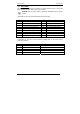
Operating Manual 9 alpha DO 1000 TECHNICAL SPECIFICATIONS Dissolved Oxygen Range mg/l of Oxygen % Saturation of Oxygen Resolution mg/l of Oxygen % Saturation of Oxygen Relative Accuracy mg/l of Oxygen % Saturation of Oxygen No.
Operating Manual alpha DO 1000 EMC Specifications Emissions Susceptibility According to EN 50081-1 According to EN 50082-1 Environmental Conditions Ambient temp. operating range Relative humidity 0 to 50 °C 10 to 95%, non-condensing Mechanical Specifications Dimensions (control panel housing - L x H x W) Weights (control panel housing) Material Insulation (Front / Housing) 175 x 96 x 96 mm max. 0.7 kg ABS with polycarbonate (front housing) IP 54 / IP 40 10 ACCESSORIES 10.
Operating Manual alpha DO 1000 11 GENERAL INFORMATION 11.1 Warranty Eutech Instruments warrants this product to be free from significant deviations in material and workmanship for a period of one year from the date of purchase. If repair is necessary and has not been the result of abuse or misuse within the warranty period, please return by freight pre-paid and amendment will be made without any charge. Eutech Instruments’ Customer Service Dept.
Operating Manual alpha DO 1000 12 APPENDICES ENSURE that the power cable is physically separated from the power supply. 12.1 Appendix 1 – Jumper Positions for 110 or 230 volts Jumper Positions - Internal to the controller JP 1 Selects the input voltage 220 VAC. JP 2 Selects the input voltage 110 VAC. Note that there is a fuse (slow-blow 100mA) internal to the Fuse controller. Replace fuse with the recommended type only.
Operating Manual alpha DO 1000 12.2 Appendix 2 – Salinity vs Temperature (@ 760 mmHg) The following table shows the Dissolved Oxygen values at different salinity values, at different temperatures, at barometric pressure of 760 mmHg. For other pressure levels, the controller automatically corrects the value based on the pressure value input. Temperature o C F 0 32.0 1 33.8 2 35.6 3 37.4 4 39.2 5 41.0 6 42.8 7 44.6 8 46.4 9 48.2 10 50.0 11 51.8 12 53.6 13 55.4 14 57.2 15 59.0 16 60.8 17 62.6 18 64.4 19 66.
Operating Manual alpha DO 1000 12.3 Appendix 3 - Explanation on the Function of Hysteresis SP1 Set to LO SP2 Set to HI RELAY ON RELAY OFF 10.0 SP1 100.0 100.5 mS 10.5 SP2 FORWARD DIRECTION HYSTERESIS BAND REVERSE DIRECTION The controller relay activates when the set-point is reached. In the reverse direction, it does not de-activate when the value reaches the set-point. Instead, it continues to be active till the value reaches the amount set by the Hysteresis band.
Operating Manual alpha DO 1000 12.4 Appendix 4 – Limit and Proportional Control Functions MIN Function MAX Function 100 % Yh 50 % 0% - Xw + Xw Xp Xp Prop. Band SP 1 Prop.
For more information on Eutech Instruments products, contact your nearest Eutech Instruments distributor or visit our website listed below: Manufactured by: Eutech Instruments Pte Ltd. Blk 55 Ayer Rajah Crescent #04-16/24 Singapore 139949 Tel: (65) 6778 6876 Fax: (65) 6773 0836 E-mail: marketing@eutechinst.com Web-site: http://www.eutechinst.