Instruction Manual αlpha-CON 1000 Conductivity Controller/Transmitter Technology Made Easy ...
Preface This manual serves to explain the use of the αlpha-CON1000 series Conductivity controller/transmitter. The manual functions in two ways: firstly as a step-by-step guide to help the user operate the instrument. Secondly, it serves as a handy reference guide. This instruction manual is written to cover as many anticipated applications of the αlpha-CON1000 Conductivity controller/transmitter.
Safety Information The Eutech Controller/ Transmitter shall be installed and operated only in the manner specified in the Instruction manual. Only skilled, trained or authorized person should carry out installation, setup and operation of the instrument. Before powering up the unit, make sure that power source it is connected to, is as specified in the top label. Failure to do so may result in a permanent damage to the unit. The unit has live and exposed parts inside.
TABLE OF CONTENTS 1 INTRODUCTION ................................................................................ 1 1.1 1.2 2 Description of Unit ..............................................................................................1 Applications .........................................................................................................1 ASSEMBLY AND INSTALLATION ................................................... 2 2.1 2.2 3 Measurement and Control System........................
7.4 Controller (Cntr) sub-function.........................................................................17 7.4.1 7.4.2 7.4.3 7.4.4 7.4.5 7.5 Measurement Range sub-function ...................................................................20 7.5.1 7.6 7.7 7.8 Entering the Configuration sub-function .................................... 22 Selecting Filter Function and the Alarm or Wash Function ....... 22 Selecting the alarm time lag .......................................................
1 1.1 INTRODUCTION Description of Unit Thank you for purchasing the ¼ DIN alpha-1000 series Conductivity process controllers. This unit is used for measuring the Conductivity of a solution, either in micro-Siemens or milli-Siemens, one at a time, and the operational mode is switchable from the menu. You can use this unit to measure Conductivity with limit control. This controller has many user-friendly and safety features which include: • • • • • • • • • • • • • • • 1.
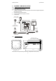
αlpha-CON1000 Operating Instructions 2 ASSEMBLY AND INSTALLATION 2.1 Measurement and Control System A typical measurement system consists of: • a αlpha-CON1000 process controller • a suitable Conductivity electrode with the appropriate Cell constant and integrated temperature sensor Pt 1000 or Pt 100, • an immersion, flow or process assembly • a final control element such as pump or valve and • a chart recorder.
αlpha-CON1000 Operating Instructions 3 ELECTRICAL CONNECTION ENSURE that the power cable is physically separated from the power supply. 3.1 Connection Diagram Cond. S/ V 18 19 20 21 22 PE/S Pt 100 Signal Input Conductivity Relay 2 Relay 1 Power Mains Hold Input Alarm Signal Output Cond.
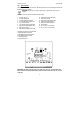
αlpha-CON1000 Operating Instructions 3.2 Back Panel The back panel consists of two connectors. The first connector is the 17-way PCB edge connector and the other is the 5-way connector. ENSURE that the power cable is physically separated from the power supply. Connection for the 17-way screw terminals (from left to right): 1. 2. 3. 4. 5. 6. 7. 8. 9.
αlpha-CON1000 Operating Instructions 4 OVERVIEW 4.1 4.1.1 Keypad and Display Keypad • Perform rapid calibration • • • • Allows entry to Set up mode Select individual functions within the function group of Set up mode Store input data in the Set up mode Start calibration in the calibration mode • Select various function groups in the Set up mode.
αlpha-CON1000 Operating Instructions 4.2 Function Groups The main function and sub-function groups are organised in a matrix format for configuration and selection of parameters. The main function groups are: Temperature Coefficient settings (tc). See Section 7.1. o Temperature Measurement / compensation settings (SEt C). See Section 7.2. Control relay 1 configuration (SP1). See Section 7.3. Control relay 2 configuration (SP2). See Section 7.3. Control type (Cntr). See Section 7.4. Current output (rng).
αlpha-CON1000 Operating Instructions 4.3 Control Concept The main function and sub-function groups are organised in a matrix format as shown below. These functions can be accessed via the front keypad for configuration and selection of parameters. MEASURE CODE tc Temp Coeff Pur / Lin Set Coeff SET C Switch On / Off ATC Process temp. (MTC) Calib. temp.
αlpha-CON1000 Operating Instructions 5 5.1 MEASUREMENT Display in Measurement mode When the controller is initially powered on, it automatically enters into the Measurement mode after the large dual LCD displays all segments briefly. The upper display shows the measured Conductivity value, while the lower display shows the temperature value. Annunciators at the right side of the display indicate whether the controller is set for µS or mS measurement.
αlpha-CON1000 Operating Instructions 5.2 Security Codes This controller has two levels of security protection with separate security codes. The first level allows entry into the Calibration mode: security code = 11; the second allows entry into the SETUP mode: security code = 22. The security codes protect the controller from unauthorised tampering of its current setting. The parameters cannot be changed unless the security code is entered. 5.2.
αlpha-CON1000 Operating Instructions 5.2.2.1 Clearing the Advanced Setup security code from the display After you have entered the security code and returned to the Measurement mode, the security code “22” still appears on the display whenever you press the ENTER key. To conceal the security code, you must manually reset the code. To clear the Advanced Setup security code from the display: 1) Press the ENTER key in the Measurement mode.
αlpha-CON1000 Operating Instructions 6 CALIBRATION MODE You can reach the Calibration mode directly from the Measurement mode by pressing the CAL key and entering the Calibration security code. You can also reach the Calibration mode from the Advanced Setup mode. 6.1 Conductivity Calibration Calibration is always carried out in the specific range selected. The Conductivity Controller allows a one-point calibration. 1) HOLD SETUP Enter Calibration mode.
αlpha-CON1000 Operating Instructions 7 ADVANCED SET-UP MODE 7.1 Temperature Coefficient sub-function This sub-function allows you to select the correct temperature coefficient for optimum operations. For applications in the pure water or ultra-pure water industries, simply select the “Pur” temperature coefficient option. For all other applications, select “Lin” temperature coefficient.
αlpha-CON1000 Operating Instructions 7.2 1) 2) 3) 4) 5) 6) 7) 8) Temperature Calibration (ATC mode only) HOLD Enter Advanced Set-up mode. Push the ENTER key and (use ▲ or ▼ keys to) scroll to Advanced Set-up security code “22”. Push the ENTER key again. Press the ▲ or ▼ keys to scroll until the display shows “SEt ºC”. Push ENTER key. Press the ▲ or ▼ keys to select “on ATC”. Press ENTER key. HOLD The upper display indicates the current temperature offset.
αlpha-CON1000 Operating Instructions 8) 9) Press ENTER key to confirm your selection. Continue with additional Additional Set-up procedures, or return to Measurement mode by pressing the ▲ and ▼ keys (escape) simultaneously). 7.3 Control Relay A/Control Relay B (SP1/SP2) sub-function The SP1 option sets the operating parameters for Relay A; and SP2 for relay B. Since these groups have the same set-up parameters, they are described together. HOLD SETUP HOLD Sp1 100 6 7.3.
αlpha-CON1000 Operating Instructions 7.3.3 Choosing High or Low set points Select a low set point to activate controller when the conductivity value undershoots the low set point; select a high set point to activate controller when the value overshoots the high set point. Using both SP1 and SP2, you can select lo/lo, lo/hi, hi/lo, or hi/hi set points (Default: SP1 = Lo; SP2 = Lo). 1) Follow directions in 7.3.1 to enter Control Relay mode. 2) Press the ENTER key.
αlpha-CON1000 Operating Instructions 7.3.5 Setting an on-delay time lag You can set as time delay for each relay, which stops the relay from switching on the moment the set point is exceeded. This controller lets you set a 0 to 1999 seconds time delay before the relay activates. 1) 2) 3) 4) 5) Follow directions in 7.3.1 to enter Control Relay mode. HOLD SETUP Press the ENTER key. Scroll with the ▲ and ▲ keys until the upper display shows “0” time and the lower display shows “On.d”.
αlpha-CON1000 Operating Instructions 7.4 Controller (Cntr) sub-function You can set the controller’s parameters in this sub-function. HOLD SETUP HOLD HOLD HOLD SETUP SETUP L.c EE YP EL SETUP FF YP HOLD SETUP PLC YP HOLD SETUP PFC YP 7.4.1 Entering the Controller sub-function 1) Enter Advanced Set-up mode. Push the ENTER key and scroll to Advanced set-up security code “22”. Push the ENTER key again. 2) Press the ▲ or ▼ keys to scroll until the upper display shows “Cntr”.
αlpha-CON1000 Operating Instructions 7.4.2 Choosing the controller type (limit or proportional) This mode lets you choose your controller type: limit control, pulse length proportional control, pulse frequency proportional control, or control off. - Use limit control with pumps or values for fast response. - Use pulse frequency proportional control to operate your pumps smoothly - Use pulse length proportional control for precise control of proportional valves.
αlpha-CON1000 Operating Instructions 7.4.4 Selecting Proportional Range Value, Xp Note: If the controller type “oFF” is set, the parameters listed in 7.4.3, 7.4.4, and 7.4.5 are blanked out. This mode lets you set a band as a percentage of its full scale value. You can select this range from 10 to 200%, and the lower display shows “PrP”. 1) Follow directions in 7.4.1 to enter Controller mode. HOLD SETUP 2) Press the ENTER key. Follow directions in 7.4.
αlpha-CON1000 Operating Instructions 7.5 Measurement Range sub-function In this sub-function, the appropriate range is selected with the appropriate cell constant. HOLD SETUP 7.5.1 Selecting the Measuring Range sub-function 1) Enter Advanced Set-up mode. Push the ENTER key and scroll to Advanced Set-up security code “22”. Push the ENTER key HOLD SETUP again. µS 2) Press the ▲ or ▼ keys to scroll until the upper display shows “rng”. 3) Press the ENTER key.
αlpha-CON1000 Operating Instructions 7.6 Current Output (rng) sub-function This sub-function lets you set the transmitter current output range of this unit. The difference between the upper and lower range has to be a minimum of 20% of Full Scale, anywhere on the scale. 7.6.1 Entering current output sub-function 1) Enter Advanced Set-up mode. Push the ENTER key and scroll to Advanced Set-up security code “22”. Push the ENTER key again.
αlpha-CON1000 Operating Instructions 7.6.4 Selecting Conductivity value at 20mA This parameter lets you choose the conductivity value at which the transmitter output will be 20mA. 1) Follow directions in 7.6.1 to enter Current Output mode. 2) Press the ENTER key. Scroll with the ▲ or ▼ keys until the upper display shows a conductivity value and the lower display shows “r.20”. 3) Press the ▲ or ▼ keys to select the required conductivity value to be equivalent to 20 mA (20.0 to 100.0% F.S.
αlpha-CON1000 Operating Instructions 7.7.3 Selecting the alarm time lag This parameter group lets you select a period of time before the alarm activates when your set point has been overshot. You can select from 0 to 1999 seconds. 1) Follow directions in 7.7.1 to enter Configuration mode. 2) 3) 4) 5) HOLD 3) 4) 5) 30 Al. Press the ENTER key. Scroll with the ∆ or ∇ keys until the upper display shows a numerical value (in seconds) and the lower display shows “AL.d”.
αlpha-CON1000 Operating Instructions 5) Proceed to 7.7.6, or return to Measurement mode by pressing the ▲ and ▼ keys simultaneously (escape). 7.7.6 Input Line Resistance Adjust This function compensates for the line resistance of the cable to its cell. 1) 2) 3) 4) 5) 7.7.7 Follow directions in 7.7.1 to enter Configuration mode. Press the ENTER key. Scroll with the ▲ or ▼ keys until the upper display shows “0.0” and lower display shows “L.Ad”. L.Ad = line adjuster resistance (0.0 to 100.
αlpha-CON1000 Operating Instructions 8 AUTO/MANUAL MODE Regardless of the mode, you can control devices connected to Relay A or Relay B from the front panel of this controller. In Automatic mode, the controller’s set point values activate the relays. In Manual mode, you have manual control of the relays so you can prime the pump or check pump status without operating the entire system. 8.1 Auto mode (mode after switch-on) In this mode, the controller set-point values activate the relays.
αlpha-CON1000 Operating Instructions 9 TECHNICAL SPECIFICATIONS Conductivity Range 0.000 to 1.999 µS/cm 0.00 to 19.99 µS/cm 0.0 to 199.9 µS/cm 0 to 1999 µS/cm 0 to 5000 µS/cm 0.00 to 19.99 mS/cm 0.0 to 199.9 mS/cm Resolution 0.001 µS/cm 0.01 µS/cm 0.1 µS/cm 1 µS/cm 5 µS/cm 0.01 mS/cm 0.
αlpha-CON1000 Operating Instructions 10 ACCESSORIES Assembly Accessories Product Description Code no. Conductivity Cell, up to 20µS; Cell constant, K=0.01 with integrated Pt 100, EC-CS10-0-01S Material SS316 and 25ft cable (open-ended) Conductivity Cell, up to 20µS; Cell constant, K=0.01 with integrated Pt 100, EC-CS10-0-01T Material Titanium and 25ft cable (open-ended) Conductivity Cell, 0.1 - 200µS; Cell constant, K=0.
αlpha-CON1000 Operating Instructions 11.4 Guidelines for Returning Unit for Repair Use the original packaging material, if possible when shipping the unit for repair. Otherwise wrap it with bubble pack and use a corrugated box for better protection. Include a brief description of any faults suspected for the convenience of Customer Service Dept., if possible. 12 APPENDICES ENSURE that the power cable is physically separated from the power supply. 12.
αlpha-CON1000 Operating Instructions 12.2 Appendix 2 – Measurement Ranges available in the Controller Range No. 1 2 3 4 5 6 7 8 9 0 Range 0.000 – 1.999 µS 0.00 – 19.99 µS 0.00 – 19.99 µS 0.0 – 199.9 µS 0.0 – 199.9 µS 0 – 1999 µS 0 – 5000 µS 0.00 – 19.99 mS 0.0 – 199.9 mS 0.0 – 199.9 mS Resolution 0.001 µS 0.01 µS 0.01 µS 0.1 µS 0.1 µS 1 µS 5 µS 0.01 mS 0.1 mS 0.1 mS Default cell K 0.01 0.01 0.1 0.1 1.0 1.0 1.0 1.0 10.0 1.0 12.
αlpha-CON1000 Operating Instructions Substance H3PO4 (15oC) NaCl Na2SO4 HCl H2SO4 CuSO4 CH3COOH Na2CO3 KCl Concentration wt % 10 20 40 45 50 5 10 15 20 25 5 10 15 5 10 20 30 40 5 10 20 40 50 60 80 100.14 5 10 20 30 1 10 15 20 30 40 5 10 15 5 10 15 20 25 Conductivity 10-4 S/cm 566 1129 2070 2087 2073 672 1211 1642 1957 2153 409 687 886 1969 3124 3463 662 5152 2085 3915 6527 6800 54055 3726 1105 187 109 189 320 421 5.84 15.26 16.19 16.05 14.01 10.
αlpha-CON1000 Operating Instructions Substance KBr (15 C) KCN (15 C) NH4Cl (NH4)2SO4 Concentration wt % 5 10 20 3.25 6.5 5 10 15 20 25 5 10 20 30 Conductivity 10-4 S/cm 465 928 1907 507 1026 918 1776 2586 3365 4025 552 1010 1779 2292 Conductivity Coefficient 2.06 1.94 1.77 2.07 1.93 1.98 1.86 1.71 1.61 1.54 2.15 2.03 1.93 1.91 12.
αlpha-CON1000 Operating Instructions 12.5 Appendix 5 - Simple Explanation on the Function of Hysteresis SP1 Set to LO SP2 Set to HI RELAY ON RELAY OFF 10.0 100.0 100.5 mS 10.5 SP2 SP1 FORWARD DIRECTION HYSTERESIS BAND REVERSE DIRECTION The controller relay activates when the set-point is reached. In the reverse direction, it does not deactivate when the value reaches the set-point. Instead, it continues to be active till the value reaches the amount set by the Hysteresis band.
αlpha-CON1000 Operating Instructions 12.
For more information on Eutech Instruments products, contact your nearest Eutech Instruments distributor or visit our website listed below: Manufactured by: Eutech Instruments Pte Ltd. Blk 55 Ayer Rajah Crescent #04-16/24 Singapore 139949 Tel: (65) 6778 6876 Fax: (65) 6773 0836 E-mail: marketing@eutechinst.com Web-site: http://www.eutechinst.