
Instruction manual
Instruction Manual αlpha CON 2000
22
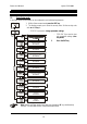
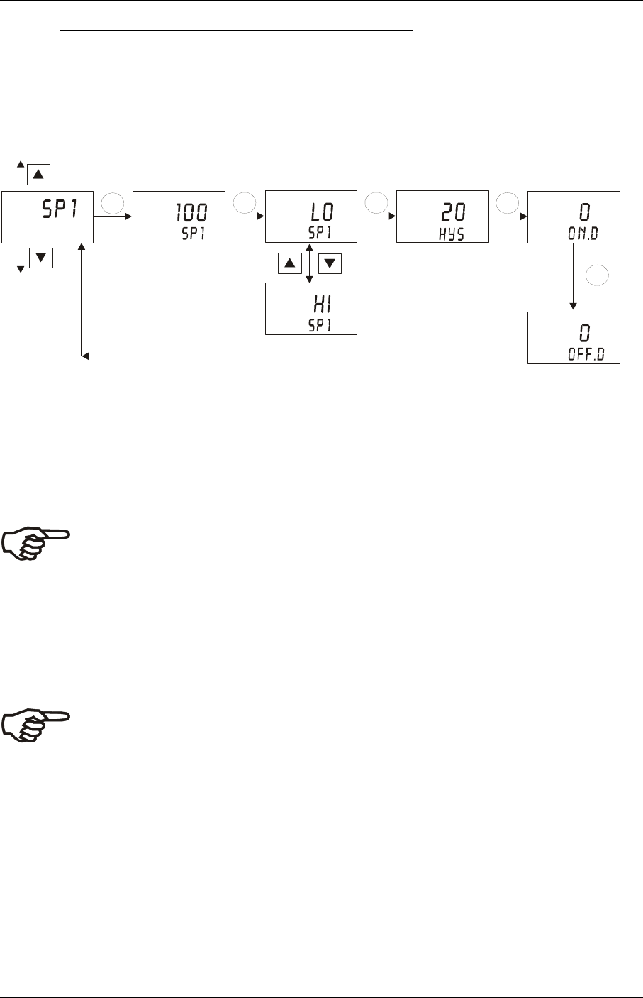
6.4 Control Relay A / Relay B (SP1/SP2) sub-function
The SP1 sub-function determines the operating parameters for Relay A; while SP2 defines the
operating parameters for Relay B. Since these groups have the same set-up parameters, they
are described together.
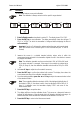
SETUP
SETUP
HOLD
HOLD
4
4
ENT
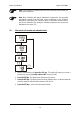
SETUP
SETUP
HOLD
HOLD
4
4
ENT
SETUP SETUP
SETUP
HOLD
HOLD
HOLD
4
4
4
ENT ENT
ENT
µS
1. Select the “SP1” (Relay A) or “SP2” (Relay B) sub-function, then press the ENT key.
2. Setting set point value: press the ▲ or ▼ key to enter the value for set point 1 (set
point 2) at which your controller will activate. Press the ENT key to confirm your setting.
3. Selecting relay function: press the ▲ or ▼ key to select the desired relay function
(“LO”= low or “HI”= high). Press the ENT key to confirm your selection.
Note: Note: This parameter lets you choose the relay function. Select “LO” to
activate the relay when the conductivity value undershoots the low set point; select
“HI” to activate the relay when the value overshoots the high set point. SP1 and
SP2 can be selected as “Lo/Lo”, “Lo/Hi”, “Hi/Lo”, or “Hi/Hi”.
4. Setting a hysteresis value: press the ▲ or ▼ key to select the desired hysteresis
(setting range: 0 to 10% of full scale) for set point 1 (set point 2). Press the ENT key to
confirm your setting.
Note: Hysteresis prevents rapid contact switching if your value is fluctuating near
the set point. Please refer to Appendix 3 for a graphical representation of the
hysteresis.
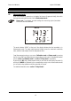
Example: You have set your high set point at 1900 µS and your hysteresis value is 20 µS. If
your measured value overshoots 1900 µS, the controller’s relay activates. The actions of the
external device will cause the solution’s conductivity to drop. The relay will deactivate, when
the conductivity value drops below 1880 µS.