Alpha CON 100 C/CX Conductivity Controller / Transmitter INSTRUCTION MANUAL 888 uS/mS o C SETU READY MODE ENTER RELAY Technology Made Easy ...
Preface This manual serves to explain the use of the Alpha CON 100 Conductivity Controller/Transmitter. The units covered are Alpha C and CX Conductivity Controller/ Transmitter. The instruction manual functions in two ways: first, as a step by step guide to help you operate and understand the operation of the unit and second, as a handy reference guide. The information presented in this manual is subject to change as improvements are made, and does not represent a commitment of Eutech Instruments Pte Ltd.
TABLE OF CONTENTS 1. INTRODUCTION 1 2. GETTING ACQUAINTED 3 2.1 Front Panel 2.2 The Back Panel 2.3 Selecting Conductivity Measurement Range 2.4 Wiring 3. OPERATING THE CONTROLLER The Main Display 4. SETTING UP THE CONTROLLER 4.1 Setting and Changing the Password 4.2 Setting the Controller Range (Software) 5. CALIBRATING THE CONTROLLER 5.1 The Lower Level Menus 5.2 Calibrating for Conductivity Measurement 5.3 Calibrating the Controller for Temperature Measurement 5.4 Setting the Alarm Feature 5.
1. INTRODUCTION The alpha CON 100 series Conductivity Controller/Transmitter is an addition to the line of process controllers from Eutech Instruments. Incorporated with the ASIC (Application Specific Integrated Circuit) microprocessor technology, this panelmounted on-line controller provides many user-friendly features desirable in conductivity Controllers. This versatile conductivity controller can be used for measuring and controlling the Conductivity of a wide range of solutions in process streams.
Some of the features of this Controller are : • • • • • • • • • • • 2 Automatic temperature compensation (with PT 100) Manual temperature compensation setting without the temperature probe Adjustable temperature coefficient from 0.0 to 10.
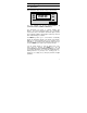
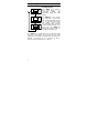
2. Getting Acquainted 2.1 Front Panel The front panel consists of a 3 digit LED display together with 5 LED annunciators. There are also 4 keys as shown below. 888 uS/mS o C SETUP MODE ENTER READY RELAY The keys available are the ▲ (UP/INCREMENT), (DOWN/DECREMENT), MODE and ENTER keys. ▼ The annunciators are µS/mS, °C, SETUP, READY, and RELAY. The µS/mS annunciator lights up in Conductivity measurement mode. The READY annunciator lights up when the Conductivity stabilizes.
2.2 The Back Panel The back panel consists of two connectors. The first one is a 4way screw terminal and the second is a 12-way screw terminal. Refer to the label on top of the unit for diagram. The connection for the 4-way screw terminals are (from the left to right): 1. PT 100 connection 2. PT 100 connection 3. Conductivity input (Inner core) 4. Conductivity input (Outer shield) The connections for the 12-way screw terminals are (from left to right), 5. High Set Relay deactivated position 6.
2.3 Selecting Conductivity Measurement Range You can set the appropriate conductivity measurement range from the front panel. See Section 4.2 for details on Setting the Controller Range (Software). Note that for “mA” the LED display shows “mA”. 2.4 Wiring Connect the power supply to the GND (EARTH) - 13 or 14, NEUTRAL - 15 and LIVE - 16 screw terminals. Make sure that the power supply jumper setting matches the mains voltage (110 VAC or 220 VAC).
3. Operating the Controller The Main Display 7.4 MODE ENTER uS/mS 24.0 MODE ENTER o C SEt SETUP MODE ENTER Press MODE key to switch to three main displays - the Conductivity display, the temperature display and “SEt” display. Press MODE key once to get into the temperature measurement. The °C annunciator lights up when you are measuring temperature. The display shows current measured temperature (with ATC) or the temperature that was set in MTC mode.
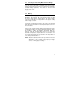
4. Setting Up the Controller 4.1 4.1.1 Setting and Changing the Password Setting New Password To set a password, press MODE key until the “SEt” is displayed. MODE 1. Press ENTER key and the ENTER display shows "CAL” and SETUP “Con” alternately. Press ▲ key once and the display shows “Set” “id”. MODE 2. Press ENTER to enter your ENTER desired password. Follow the SETUP steps below (e.g. using a password “123”). MODE 3. Initially, the display shows "000" with the first digit blinking. ENTER 4.
To calibrate the controller at any time, you may have to enter the password that you set, in order to access the calibration mode. Once you have entered the password correctly, the display shows "CAL COn” indicating that you are in one of the lower-level SETUP menus. If you enter the wrong password, the display reverts back to the Conductivity display.
4.2 Setting the Controller Range (Software) At the measurement mode, press both ▲ and ▼ keys simultaneously until the “CLr” display shows. Press ▲ or ▼ key to select the appropriate Conductivity measurement range. Press ENTER key to confirm. CLr MODE ENTER uS/mS 999 MODE ENTER uS/mS Cell Constant either 0.1 or 1.0 blinks when the 999 uS range is selected 1.
5. Calibrating the Controller 5.1 The Lower Level Menus The "CAL COn" display is the first menu seen upon entering the lower-level menus. Press ▲ or ▼ key to display the various menus as shown in the figure below. Press ENTER key to go to the lower level menus. START o CAL C 5.2 2. 3. 4. 10 Hi SEt Hys Hi Lo SEt Hys Lo Calibrating for Conductivity Measurement 5.2.1 1.
5. When “CAL COn” displays, press ENTER key to view the default cell constant at 100%. Press ENTER key again to show MODE the measured conductivity value. ENTER Use ▲ and ▼ keys to scroll to SETUP the standard’s Conductivity value at 25 oC. 6. Press ENTER key to calibrate MODE the Conductivity value shown. ENTER Display will show the new cell SETUP constant being displayed. This value will be between 70% to 130%.
5.3 Calibrating the Controller for Temperature Measurement The CAL °C menu 1. Enter this menu by pressing MODE MODE key twice to the “SEt” display ENTER if you are in measurement mode. SETUP 2. Press ENTER key. If the password has been set earlier, key in the password using the method described in section 4.1. Press MODE ENTER once to confirm. After you ENTER set the correct password, you see SETUP the “CAL” and “COn” display blinks alternatively. Press ▼ key once, the display shows “CAL” “oC” blinking.
ATC OFF : If a PT 100 is not used, then the ATC should be set to OFF. In step 3 above, choose by pressing ▲ and ▼ keys to select ATC OFF. Then press ENTER. The display will now show the default of 25 oC or the last set value (blinking). Use ▲ and ▼ keys to set your desired value. Press ENTER to confirm and the display shows “CAL” “Con”. Note : For ATC OFF, you can adjust the set temperature values from 0.0 to 99.9 oC. This value will be used for its temperature compensation e.g.
5.4 Setting the Alarm Feature This menu allows you to change the Hi and Lo Setpoint and Hysteresis values. See Section 8 for hysteresis applications. IMPORTANT : When SETUP mode is entered, the 4-20 mA output (only for transmitter model) freezes and the relay deactivates (if it was in an alarm condition). 5.4.1 SEt 1. Enter this menu by pressing MODE key twice to the “SEt” display if you are in measurement mode. 2. Press ENTER key.
5.4.2 The Hi HYS Menu 1. Enter this menu by pressing the MODE key to the “SEt” display if you are in the measurement mode. 2. Press ENTER key. If the password has been set earlier, key in the password using the method described in section 4.1. Press ENTER once to confirm. After you set the correct password, you see the “CAL” and “COn” display blinks alternatively. Press ▼ key thrice, the display shows “Hi” “HYS” blinking. 3.
5.4.3 The Lo SEt Menu 1. Enter this menu by pressing MODE MODE key twice to the “SEt” display if you are in measurement ENTER mode. SETUP 2. Press ENTER key. If the password has been set earlier, key in the password using the method MODE described in section 4.1. Press ENTER ENTER once to confirm. SETUP 3. After you set the correct password, you see the “CAL” and “COn” display blinks alternately. Press ▼ key four times, the display MODE shows “Lo” “SEt” blinking ENTER alternately. SETUP 4.
5.4.4 The Lo HYS Menu 1. Enter this menu by pressing the MODE key to the “SEt” display if you are in the measurement mode. 2. Press ENTER key. If the password has been set earlier, key in the password using the method described in section 4.1. 3. Press ENTER once to confirm. After you set the correct password, you see the “CAL” and “COn” display blinks alternatively. Press ▼ key five times, the 4. 5.
5.5 Setting Temperature Coefficient 5.5.1 Temperature Coefficient This menu allows you to set the Temperature Coefficient corresponding to the solution whose Conductivity is being measured. In most controllers, this is fixed at 2.10% per oC. However, for alpha CON 100 C/CX models, it is adjustable from 0.0 to 10.0% per oC (please refer to Appendix 3 for Temperature Coefficient determination and limits). 1.
6. Setting to Factory Default All the controller settings and user-defined password, except calibration data will be cleared when you enter into the “Usr” “Clr” menu. Press both the ▲ and ▼ keys simultaneously while you are in any mode menu. The unit requests for the password if it was set previously. Enter the password and press ENTER. The display will show “CLr”. Press ENTER to confirm. The display will blink briefly - the password is reset to its factory default and toggles to its measurement mode.
7. Using the Controller Current Loop for Datalogging (for Transmitter Model Only) The 4-20 mA Current Loop A 4-20 mA current loop can be connected if a remote data logging is required. The current will be proportional to the Conductivity displayed on the panel display. The 4-20 mA current loop can drive a load resistance of no more than 200Ω. If the calculated Conductivity is less than 0 uS (due to incorrect TC and temperature setting), the current will be set to approximately 0 mA.
8. Additional Information The controller allows you to set High and Low alarms that switch on or off relays, and activating or deactivating devices linked to the controller. In cases where the Conductivity values fluctuate close to the high or low setpoints, the relays will continuously switch on/off very quickly and may cause problems to the linked devices. The hysteresis band allows you to set an allowable range of fluctuations to prevent the relays from activating and deactivating too quickly. See below.
Explanation of the diagram in the previous page A - Reading reaches (Hi SET - ½ HI HYS), the Hi-Set relay remains inactivated. B - Reading reaches above High Setpoint but below (Hi SET + ½ Hi HYS), Hi-Set relay remains inactivated. C - Reading reaches between (Hi SET - ½ Hi HYS), the Hi-Set relay remains inactivated. D - Reading reaches above (Hi SET + ½ Hi HYS), and the HiSet relay is activated. E - The Hi-Set relay is inactivated only when the reading falls below (Hi SET - ½ Hi HYS).
Appendix 1 Jumper Positions - Internal to the Controller JP1 Fuse Selects the input voltage between 110 VAC or 220 VAC. Note that there is a fuse internal to the Controller. Before opening the unit, ENSURE that the power cable is physically separated from the mains supply. Replace the fuse with the one recommended by the manufacturer.
Appendix 2 Temperature Coefficient The Temperature Coefficients (TC) of most solutions vary between 1.8 to 2.4 % per oC. This is true of most salt solutions when the Conductivity exceeds about 100 uS. Thus, the default value of TC will be set to 2.10 % per oC when the Controller is shipped from the factory. However, if the Temperature Coefficient is known to be different from the default, the user can set this value.
Technical Specifications Specifications Conductivity Range Relative Accuracy Cell Constant Measurement Range Calibration Temperature Coefficient Temperature Compensation Temperature Resolution Relative Accuracy Sensor Output Display Inputs Recommended Input Cable Length Relays No. Of Relays Maximum Voltage Maximum Current High Hys. Band Low Hys. Band Power Requirements Environmental Requirements Operating Storage Humidity Limits Storage Temp. Range Dimensions Range Resolution Cell Constant 0.1 0.1 1.
NOTES 26