Digi –Sense ® INSTRUCTION MANUAL Temperature Controller R/S (Standard Model) 68900-01 68900-03 Eutech Instruments Pte Ltd Blk 55 Ayer Rajah Crescent #04-16 Singapore 139949 Tel: (65) 6778 6876 Fax: (65) 6773 0836 Website: www.eutechinst.com email: marketing@eutechinst.com 68X329501 Rev.
TABLE OF CONTENTS Title Page SAFETY PRECAUTIONS ...................................................................... 1 INTRODUCTION .................................................................................... 2 APPLICATION DATA .............................................................................. 3 DESCRIPTION ....................................................................................... 3 GENERAL .................................................................................
TABLE OF CONTENTS (Continued) Title Page Cycle Time ................................................................................. 18 Run Time .................................................................................... 18 Power Up Control ....................................................................... 19 OPERATION ........................................................................................ 20 RUN MODE .........................................................................
SAFETY PRECAUTIONS DANGER: There are no user-serviceable parts in this instrument. Do not remove cover, as high voltages exist inside the unit. Refer servicing to your dealer. DANGER: If thermocouples are at a high voltage, this voltage will be present at other points inside the unit. DANGER: For continued fire protection, replace fuse only with a fuse of the specified current, voltage, and type. Remove power cord from wall socket before checking or replacing a fuse.
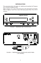
INTRODUCTION This manual provides information for installing and operating the Temperature Controller (standard model). Refer to Figure 1 for a view of the front panel of the Temperature Controller. Refer to Figures 2 and 3 for a view of the back panels of the 115 or 230 V versions. FIGURE 1. TEMPERATURE CONTROLLER FIGURE 2.
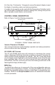
FIGURE 3. TEMPERATURE CONTROLLER, BACK PANEL (230 V MODEL) APPLICATION DATA Applications for the Temperature Controller include heating and cooling of solids, liquids, and gases. For all applications, there are certain set-up operations that should be made carefully to assure optimum and safe performance.
kit. A two-line, 16-character, 14-segment vacuum fluorescent display is used for display of operating, setup, and alarm parameters. A number of accessories can be used with this Temperature Controller, including various types of temperature sensors, heating units, cooling units (such as fans or pumps), remote alarms, and recorders. CONTROL PANEL DESCRIPTION Refer to Figure 4 and the following paragraphs.
SET Key The SET key allows you to change the control setpoint (SP), using the arrow keys. Pressing the SET key again will exit the setpoint mode. ALARM Key The ALARM key enables you to acknowledge temperature control alarm conditions and silence the audible alarm. Pressing the ALARM key will erase any alarm messages on the display and stop the ALARM from flashing. If the alarm condition is still present, the ALARM LED will remain on until the PV (process variable) is out of the alarm condition.
2. Setup the operating parameters. Press MENU and follow the interactive setup selections. If your setup is the same as the factory set defaults, this step is not necessary. However, each of the setup options should be checked for desired or proper setting. Set sensor type that was connected. Select temperature scale. Set alarms, if desired. Calibrate system, if better accuracy is desired. Set safety stops (over temperature and loop break). Select control action and mode desired (PID or on/off). Set max.
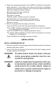
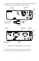
3. Plug the unit in to a correctly rated AC outlet and turn on the power using the ON/OFF switch on the back panel. Refer to Figure 5. Heater Cord Cable Connection Heater/Cooler Output Fuse ON/OFF Switch Instrument Fuse Mini-ANSI Thermocouple Jack (500 ohm Max Load Resistance) 115 V Heater Cord Cable Connection Heater/Cooler Output Fuse Power Line Cord Connection ON/OFF Switch Instrument Fuse Mini-ANSI Thermocouple Jack (500 ohm Max Load Resistance) 230 V FIGURE 5.
SETUP PROCEDURE NOTES: a. At any time during the setup procedure, you may return to the previous screen by pressing and holding down the LEFT arrow key and then pressing the MENU key. b. For experienced operators, a flow chart may be used for setup and operation. Refer to Appendix A. c. The setup mode can only be entered when the temperature controller is stopped. 1. Set the ON/OFF switch on the rear panel to ON. The LEDs will light and all segments will light temporarily as a check of the display. 2.
Temperature Scale 1. After pressing the MENU key in the THERMOCOUPLE screen, the setup will progress to the Temperature Scale selection. The Temperature scale selection has five temperature scales from which to choose: Celsius (°C), Fahrenheit (°F), Reaumur (°R'), Rankine (°R), or Kelvin (K). Refer to Figure 8. 2. Press the DOWN arrow key to switch to a desired temperature scale. Press the MENU key to select the appropriate scale. TEMP SCALE FAHRENHEIT °F FIGURE 8.
3. To select alarm setpoints off, press the MENU key when the ALARM SETPOINTS OFF screen is blinking. 4. After alarm selection, press the MENU key to move on to Alarm Hysteresis. After setting Alarm Hysteresis, press the MENU key again to move on to the Audible Alarm screen. There are three types of alarms: HI, LO and HILO. Refer to the following paragraphs for more information. HI Alarm 1. HI Alarm activates the alarm when the PV temperature exceeds the set alarm temperature. Refer to Figure 10.
LO Alarm 1. LO Alarm activates the alarm when the PV temperature drops below the alarm temperature. Refer to Figure 12. If the Control Action is set to HEAT and the PV temperature is below the alarm temperature when the RUN Key is pressed, the alarm will not be activated. The PV temperature must first rise above the alarm temperature before the low alarm is enabled. This allows for normal system startup without activating the alarm. MODE LO ALARM FIGURE 12. LO ALARM MODE SCREEN 2.
2. Select HILO by pressing the MENU key. The following screen will appear (refer to Figure 15). Set the alarm temperatures by using the arrow keys. Once the first alarm value is set, press the LEFT arrow key to adjust for the other alarm variable. ALARM SP °F HI XXXX.X LO XXXX.X FIGURE 15. HILO SETTINGS SCREEN Alarm Hysteresis 1. Alarm Hysteresis determines when the alarm is going to be out of the alarm condition. Alarm hysteresis prevents actuation of nuisance, or recurrent, alarms.
Audible Alarms Audible Alarm permits the sound of an alarm. It has two options: On or Off. Use the arrow keys to select an option and press the MENU key to advance to the Advanced Setup MENU. Refer to Figure 17. AUDIBLE ALARM ON FIGURE 17. ALARM AUDIBLE SCREEN Advanced Set-Up 1. After pressing the MENU button, the ENTER ADVANCED SETUP screen will be displayed (refer to Figure 18). 2. The flashing message YES will ask if you want to enter the Advanced Screen. Press the MENU key as the word YES blinks.
SENSOR OFFSET CAL ± XX.X XXX.X °F FIGURE 19. SENSOR OFFSET CAL NOTE: Calibration can also be done using an ice bath or boiling water and adjusting the offset until 32.0 °F or 212 °F is displayed. Over Temp Stop 1. Over temp stop temperature, a safety feature, is added to the setpoint (SP) temperature. If the PV temperature exceeds this amount, the temperature controller will stop. Over temp stop does not operate if the COOL control action is selected. Refer to Figure 20. OVER TEMP.
Loop break stop is designed to terminate the process currently running if the process is interrupted for a preset period of time. The loop break stop senses that nothing is happening in the process and turns the process off. Enter an elapsed time using the UP and DOWN arrow keys. For slow systems, a longer time should be entered. Control Action 1. The Control Action screen allows selection of the type of process that will be performed; either HEAT or COOL. Refer to Figure 22.
Control Mode On/Off 1. The Control Mode On/Off turns off the output when the actual temperature exceeds the setpoint (heat control action). The output will turn on when the actual temperature falls below the setpoint temperature minus the hysteresis temperature. Refer to Figure 24. ON/OFF CONTROL HYSTERESIS XX.X °F FIGURE 24. ON/OFF CONTROL HYSTERESIS SCREEN 2. Adjust the hysteresis value on this screen using the arrow keys. 3. Press the MENU key to advance to the RUN TIME Screen.
2. Select an option using the arrow keys. 3. If AUTO TUNE ENABLED is selected, press the MENU key four times to advance past the PID setup to the Cycle Time screen. NOTE: AUTO TUNE DISABLED is also a safety feature to prevent accidental auto tuning. Proportional Band 1. Select the proportional band by pressing the MENU key. The following screen will appear (refer to Figure 26). 2. Use the arrow keys to enter the correct value and press the MENU key. PROPORTIONAL BAND XXXX °F FIGURE 26.
Derivative Rate 1. The derivative rate reduces or eliminates overshoot. Refer to Figure 28. It is measured in seconds and must be tuned to work with the overall system cycle time. DERIVATIVE RATE XXXX SECONDS FIGURE 28. DERIVATIVE SCREEN 2. Use the arrow keys to enter the correct value and press the MENU key. Cycle Time Cycle time is the rate at which the output is cycled or changed. The manufacturer's recommended cycle time is 1 second.
1. Use the DOWN arrow key to increment the time period desired. 2. Press the MENU key to enter your selection. Power Up Control This set up option allows you to specify one of two conditions for the temperature controller at turn on. Power Up Control has two options: Last State and Stopped. Refer to Figure 31. POWER UP CONTROL LAST STATE FIGURE 31. POWER UP CONTROL SCREEN The two selections are designed primarily to function in the event of a power failure.
OPERATION Once installation and setup are complete, press the RUN/STOP key to begin operation. The following screen will appear (refer to Figure 32) if a previous run was stopped before it completed. RUN OPTION CONTINUE/RESTART FIGURE 32. RUN SCREEN Select either CONTINUE or RESTART using the arrow keys and then press RUN/STOP key. CONTINUE will start a run with the time remaining from the previous run. RESTART will reset the run time and start a new run.
TROUBLESHOOTING AND MAINTENANCE DANGER: There are no user-serviceable parts in this instrument. Do not remove cover, as high voltages exist inside the unit. Refer servicing to your dealer. DANGER: If thermocouples are at a high voltage, this voltage will be present at other points inside the unit. TROUBLESHOOTING If the heater output does not function correctly, check the fuse located on the rear of the unit left of the heater output receptacle. The fuse is rated at 10 A.
SPECIFICATIONS Display: Two lines of 16 characters. Four-digit process value. Four-digit setpoint value. Accuracy: Type J,K,T,E and N above −100°C (−148°F): ±0.1% reading, ±0.4°C (±0.7°F) below −100°C (−148°F): ±0.1% reading, ±1°C (±1.8°F) Type R,S and B ±0.1% reading, ±1°C (±1.8°F) Resolution: Environment: Temperature, Operating: Temperature, Storage: Temperature, Specification: Humidity: Altitude: Pollution Degree: 0.1° auto-ranging to 1° above 999.
SPECIFICATIONS (Continued) Sensor Input Range/Accuracy: Thermocouples Type Range −200 to 1000°C −190 to 1000°C −200 to 1372°C −200 to 1300°C −200 to 400°C 200 to 1800°C 0 to 1768°C 0 to 1768°C E: J: K: N: T: B: R: S: (−328 to 1832°F) (−310 to 1832°F) (−328 to 2502°F) (−328 to 2372°F) (−328 to 752°F) (−392 to 3272°F) (− 32 to 3214°F) (− 32 to 3214°F) INPUTS AC Line Input 115V Model Input: Connector: Fuse: 230V Model 115V AC ±15%, 49/61 Hz 10A Max Standard Line Cord 0.
WARRANTY Eutech Instruments supplies this product with a ONE-YEAR warranty to be free from significant deviations from published specifications. If repair or adjustment is necessary within the warranty period, the problem will be corrected at no charge if it is not due to misuse or abuse on your part as determined by Eutech Instruments. Repair costs outside the warranty period, or those resulting from product misuse or abuse,may be invoiced to you.
APPENDIX A EN 400 Temperature Controller - Setup Mode for Standard Model 25 A-1
APPENDIX B The following is a list of error messages that may be displayed by the Temperature Controller and a description of corrective action. Upper Display Lower Display Action normal OVER TEMP STOP PV exceeded OVER TEMP STOP setting in user setup. normal LOOP BREAK STOP No change in PV with output on for user settable time period. Adjust LOOP BREAK STOP in user setup. normal OPEN PROBE STOP Detected open probe sensor while running. Check probe.
Temperature Controller Accessories EUTECH INSTRUMENTS STANDARD MODELS 68900-01 115V 68900-03 230V Catalog # MODEL 68900-50 68900-98 50001-78 68900-94 All models All models 230V only 230V only DESCRIPTION Panel Mount Kit Heater Sizing Software Input Cord - IEC320/NEMA 6-15P Heater Output Connector, IEC 10A 28