
User's Manual

ReliaGATE 10-12 User manual Rev. 2-1 9 Interfaces in detail
9.6 CAN 0 and CAN 1
The ReliaGATE 10-12 provides 2x CAN (Controller Area Network) ports compliant with the CAN
Specification 2.0, Parts A and B:
l CAN 0
l CAN 1
The CAN connectors are available on the front side.
For more information see: "How to manage the CAN ports" on page76.
No CAN termination resistors are present internally. If required, they need to be added externally.
Notes about CANpower supply:
l The ReliaGATE 10-12 can supply power to the 2 CAN ports: 100mA @ 5V (each port)
l CAN power can be enabled / disabled by software
l The interfaces are surge protected.
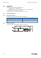
9.6.1 CAN 0 and CAN 1 connector specifications
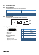
Connector Layout:
Connector Specifications:
l Base strip, Header
l Gender: Male
l Type: 8-pin, 3.5 mm pitch
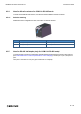
Mating Connector Specifications:
l Pluggable screw terminal block;
l Gender: Female
l Type: 8-pin, 3.5 mm pitch
l Example:
Manufacturer: Phoenix Contact
Part Number: MC 1,5/ 8-STF-3,5 - 1847181
(or equivalent)
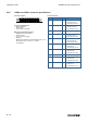
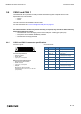
Connector Pinout:
Pin # Signal Type Description
1 CAN 0: H IO CAN port 0 Positive Data
2 CAN 0: L IO CAN port 0 Negative Data
3 CAN 0: 5V 5 CAN node 0
5 V Output power supply
4 CAN 0: GND P Ground
5 CAN 1: H IO CAN port 1 Positive Data
6 CAN 1: L IO CAN port 1 Negative Data
7 CAN 1: 5V 5 CAN node 1
5 V Output power supply
8 CAN 1: GND P Ground
59 / 118