
User's Manual


ReliaGATE 10-12 User manual Rev. 2-1
Appendix 2: Expansion connector pin map with respect to
device tree pin assignment
APPENDIX 2: EXPANSION CONNECTOR PIN MAP WITH
RESPECT TO DEVICE TREE PIN ASSIGNMENT
The ReliaGATE 10-12 provides an Expansion connector on the right side.
For more information see:
l "Right Side Interface overview" on page42
l "Expansion connector" on page62
l "How to enable the 3.3V and 5V power supply on the Expansion connector" on page86.
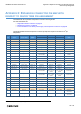
The following table shows the Expansion connector pin map with respect to the device tree
1
pin
assignment:
Pin # Signal CPU Pin Name GPIO*
DTB #1 DTB #2
Notes6x DTB SPI DTB Generic
1 VCC 3v3 EXT Power line
2 DGND Power line
3 VCC 5v_EXT Power line
4 USB_EXP+ USB1_DP USB_EXP+ USB_EXP+ USB_EXP+ USB line: fixed
5 USB_EXP- USB1_DM USB_EXP- USB_EXP- USB_EXP- USB line: fixed
6 DGND Power line
7 MCASP0_FSX LCD_DATA9 GPIO2_15 ReliaIO: CPU_RST GPIO2_15 GPIO2_15
8 MCASP0_AXR0 LCD_DATA10 GPIO2_16 Reserved: cannot be
user-controlled
GPIO2_16 GPIO2_16 Power Enable for LoRa
devices
9 MCASP0_ACLKX LCD_DATA8 GPIO2_14 ReliaIO: BOOT0 GPIO2_14 GPIO2_14
10 MCASP0_AXR1 LCD_DATA14 GPIO0_10 ReliaIO: INT_CPU GPIO0_10 GPIO0_10
11 DGND Power line
12 Reserved UART1_RXD GPIO0_14 Reserved Reserved Reserved Reserved
13 Reserved UART1_TXD GPIO0_15 Reserved Reserved Reserved Reserved
14 USB_EXP_EN USB1_DRVVBUS GPIO3_13 GPIO3_13 GPIO3_13 GPIO3_13
15 GPIO_EXP_2 LCD_DATA1 GPIO2_7 Reserved: cannot be
user-controlled
GPIO2_7
VCC_3v3_EXT
Enable
GPIO2_7
VCC_3v3_EXT
Enable
Reserved: VCC_3v3_
EXT Enable
16 GPIO_EXP_1 LCD_DATA0 GPIO2_6 Reserved: cannot be
user-controlled
GPIO2_6
VCC_5v_EXT
Enable
GPIO2_6
VCC_5v_EXT
Enable
Reserved: VCC_5v_
EXT Enable
17 DGND Power line
18 SPI1_D1 MCASP0_AXR0 GPIO3_16 SPI1_D1 SPI1_D1 GPIO3_16
19 SPI1_CS0 MCASP0_AHCLKR GPIO3_17 SPI1_CS0 SPI1_CS0 GPIO3_17
20 SPI1_D0 MCASP0_FSX GPIO3_15 SPI1_D0 SPI1_D0 GPIO3_15
21 SPI1_SCLK MCASP0_ACLKX GPIO3_14 SPI1_SCLK SPI1_SCLK GPIO3_14
22 DGND Power line
23 I2C1: SDA SPI0_D1 GPIO0_4 I2C1: SDA I2C1: SDA I2C1: SDA Reserved:
I2C internal
24 I2C1: SCL SPI0_CS0 GPIO0_5 I2C1: SCL I2C1: SCL I2C1: SCL Reserved:
I2C internal
*This column lists the GPIO pins that might be available if the default function is not used or reserved.
1
See also "The production fitImage" on page112.
115 / 118