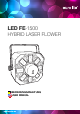
LED FE-1500 HYBRID LASER FLOWER BEDIENUNGSANLEITUNG USER MANUAL www.eurolite.
LED FE-1500 FE HYBRID LASER FLOWER Showlaser-Lichteffekt • 3-in-1-DMX-Lichteffekt mit rotem und grünem Laser, rotierendem LED-Derby und weißen Strobe-LEDs • Laserklasse 2M: keine Abnahme oder Bestellung eines Laserschutzbeauftragten erforderlich • 2 Laserdioden projizieren tausende rote und grüne Laserstrahlen • Rotierender Derby für Spiegelkugeleffekte mit fünf 3-W-LEDs (Rot, Grün, Blau, Weiß und Amber) • Acht weiße 1-W-Strobe-LEDs • Auto, Musik-, Master/Slave- und DMX-Modus • 7 integrierte Showprogramme
Inhaltsverzeichnis EINFÜHRUNG ....................................................................................................................................................4 SICHERHEITSHINWEISE ..................................................................................................................................4 BESTIMMUNGSGEMÄSSE VERWENDUNG ...................................................................................................6 BEDIENELEMENTE UND ANSCHLÜSSE ...................
1 EINFÜHRUNG Wir freuen uns, dass Sie sich für ein Produkt von EUROLITE entschieden haben. Wenn Sie nachfolgende Hinweise beachten, sind wir sicher, dass Sie lange Zeit Freude an Ihrem Kauf haben werden. Bitte bewahren Sie diese Bedienungsanleitung für weiteren Gebrauch auf. >> Lesen Sie vor der ersten Inbetriebnahme zur eigenen Sicherheit diese Bedienungsanleitung sorgfältig. Diese Bedienungsanleitung gilt für die Artikelnummer 51741080. Die neueste Version finden Sie online: www.eurolite.
Laser • Dieses Gerät beinhaltet einen Laser der Klasse 2M entsprechend der Klassifizierung nach DIN EN 60825-1:2007. Nicht in den Strahl blicken! Die zugängliche Laserstrahlung liegt nur im sichtbaren Spektralbereich (400 nm bis 700 nm). Bei kurzzeitiger Bestrahlungsdauer (max. 0,25 Sekunden) ist die Laserstrahlung jedoch ungefährlich auch für das Auge. Eine längere Bestrahlung wird durch den natürlichen Lidschlussreflex verhindert.
3 BESTIMMUNGSGEMÄSSE VERWENDUNG Anwendungsbereich • Dieses Gerät ist ein Showlaser für den Privatgebrauch und professionelle Anwendungen, z. B. auf Bühnen, in Diskotheken, Theatern etc. vorgesehen. Es eignet sich sowohl für den Mobilbetrieb als auch für Festinstallationen. • Beim Einsatz einer Lasereinrichtung in öffentlichen bzw. gewerblichen Bereichen ist eine Fülle von Vorschriften zu beachten, die hier nur auszugsweise wiedergegeben werden können.
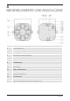
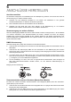
4 BEDIENELEMENTE UND ANSCHLÜSSE 1 Linsen für die RGBWA-LEDs (8) 2 Laseraustrittsöffnung 3 Weiße Strobe-LEDs (8) 4 Montagebügel 5 Netzanschluss mit Sicherungshalter 6 Netzdurchschleifausgang 7 Fangseilöse 8 Feststellschraube 9 DMX-Ausgang 10 DMX-Eingang 11 Display und Bedientasten 12 Anzeige für Musiksteuerung 13 Anzeige für DMX-Betrieb 14 Automatikbetrieb 15 Slave-Betrieb 16 Mikrofon und Empfindlichkeitsregler für Musiksteuerung www.eurolite.
5 INSTALLATION GEFAHR DURCH LASERSTRAHLUNG! Installieren Sie den Laser so, dass die Projektionen mit einem Abstand von mind. 1 Meter zum Publikum stattfinden. ÜBERHITZUNGSGEFAHR! Der Abstand zwischen der Lichtquelle und der beleuchteten Fläche muss größer als 0,1 m sein. Sorgen Sie stets für ausreichende Belüftung. Die Umgebungstemperatur muss immer unter 45 °C liegen. LEBENSGEFAHR! Achten Sie bei der Installation des Geräts darauf, dass sich im Abstand von mind.
LEBENSGEFAHR! Bei der Installation sind insbesondere die Bestimmungen der BGV C1 und EN 60598-2-17 zu beachten! Die Installation darf nur vom autorisierten Fachhandel ausgeführt werden! LEBENSGEFAHR! Vor der ersten Inbetriebnahme muss die Einrichtung durch einen Sachverständigen geprüft werden! Bei Überkopfmontage in öffentlichen bzw. gewerblichen Bereichen ist eine Fülle von Vorschriften zu beachten, die hier nur auszugsweise wiedergegeben werden können.
6 ANSCHLÜSSE HERSTELLEN Anschluss ans Netz Der Showlaser verfügt über ein Schaltnetzteil, das eine Netzspannung zwischen 100 und 240 Volt sowie die Stromversorgung von weiteren Geräten erlaubt. 1 Schließen Sie das beiliegende Netzkabel an und stecken den Netzstecker in eine geerdete Schutzkontaktsteckdose ein. Damit ist das Gerät eingeschaltet. 2 Zum Ausschalten ziehen Sie den Netzstecker aus der Steckdose. 3 Schließen Sie das Gerät nicht über einen Dimmer an die Netzspannung an.
7 BEDIENUNG Das Gerät verfügt über ein Bedienfeld mit Display, auf dem alle Betriebszustände abgelesen werden können. Nach dem Einschalten werden kurz Informationen zum Gerät angezeigt, danach die zuletzt eingestellte Betriebsart. Nehmen Sie nun die notwendigen Menüeinstellungen für die geweilige Betriebsart mit den Bedientasten vor. Auch wenn Sie das Gerät vom Stromnetz trennen, bleiben alle Einstellungen gespeichert. ► Bedientasten MODE Zur Wahl der Betriebsart.
Betrieb ohne externe Steuerung Im Automtikbetrieb stehen 7 Showprogramme zur Verfügung, die auf Wunsch vom eingebauten Mikrofon gesteuert werden können oder mit einer einstellbaren Geschwindigkeit ablaufen. Nr. 0 1 2 3 4 5 6 Beschreibung Laser + farbige LEDs + weißen Strobe-LEDs Laser + farbige LEDs Laser + weißen Strobe-LEDs Farbige LEDs + weißen Strobe-LEDs Farbige LEDs Laser Weiße Strobe-LEDs ► Automatikbetrieb 1 2 3 4 Drücken Sie die Taste MODE so oft, bis im Display die Anzeige blinkt.
DMX-Betrieb ► DMX-Startadresse einstellen Für den Betrieb über einen Controller mit DMX512-Protokoll verfügt der Showlaser über 9 Steuerkanäle. Damit der Showlaser vom Controller angesteuert werden kann, muss die DMX-Startadresse für ihren 1. DMX-Kanal eingestellt werden. Die Startadresse ist abhängig von Ihrem DMX-Controller. Lesen Sie hierzu die Dokumentation des Geräts. 1 2 3 Drücken Sie die Taste MODE so oft, bis im Display die Anzeige (für DMX) und eine Zahl zwischen 001 und 504 blinkt.
130 – 134 135 – 139 140 – 144 145 – 149 150 – 154 155 – 159 160 – 164 165 – 209 210 – 255 Amber + weiß + blau Rot + grün + blau + amber Rot + grün + blau + weiß Blau + grün + weiß + amber Rot + grün + amber + weiß Weiß + rot + blau + amber Rot + grün + blau + amber + weiß Automatischer Farbwechsel (nur eine Farbe) Automatischer Farbwechsel (zwei Farben gleichzeitig) DMX-Wert Funktion Kanal 3: Farbwechselgeschwindigkeit, wenn Kanal 2 auf einen Wert zwischen 165 und 255 eingestellt ist 000 – 255 langsam →
8 REINIGUNG, WARTUNG UND INSTANDHALTUNG GEFAHR DURCH LASERSTRAHLUNG! Wenn geöffnet, nicht in den Strahl blicken oder direkt mit optischen Instrumenten betrachten. LEBENSGEFAHR! Vor Wartungsarbeiten unbedingt allpolig vom Netz trennen. Lasereinrichtungen in Diskotheken sind technische Arbeitsmittel entsprechend dem Gerätesicherheitsgesetz. Daher müssen sie dessen Forderungen entsprechen.
9 TECHNISCHE DATEN Spannungsversorgung: Gesamtanschlusswert: Laserklasse nach EN 60825-1: Lasermodule: Wellenlänge: Farb-LEDs: Strobe-LEDs: Blitzrate: Abstrahlwinkel: DMX-Steuerkanäle: DMX512-Anschluss: Musiksteuerung: Maximale Umgebungstemperatur Ta: 100-240 V AC, 50/60 Hz 40 W 2M Rot 100 mW, grün 50 mW Rot 650 nm, grün 532 nm 5 x RGBWA, je 3 W 8 x weiß, je 1 W 0-30 Hz 17° 9 3-pol. XLR über eingebautes Mikrofon 45° C Max.
1 INTRODUCTION Thank you for having chosen a EUROLITE product. If you follow the instructions given in this manual, we are sure that you will enjoy this device for a long period of time. Please keep this manual for future needs. >> For your own safety, please read this user manual carefully before your initial start-up. This user manual is valid for the article number 51741080. You can find the latest update at: www.eurolite.
Laser • This device includes a class 2M laser according to the EN 60825-1:2007 regulation. Do not stare into the beam! The accessible laser radiation is exclusively within the visible spectral range (400 nm to 700 nm). However, a short-term exposure (max. 0.25 seconds) is not hazardous to the eye. A longer exposure is prevented by the natural eyelid closing reflex. Nevertheless, close your eyes or turn away immediately if the laser beam hits the eye.
3 OPERATING DETERMINATIONS Areas of Use • This device is designed for private and professional use, e.g. on stage, discos, clubs, bars or theatres. It is applicable for mobile use and permanent installations. • When operating a laser product in public or industrial areas, a series of safety instructions have to be followed that this manual can only give in part. The operator must therefore inform himself on the current safety instructions and consider them.
4 OPERATING ELEMENTS & CONNECTIONS 1 Lenses for the RGBWA LEDs (8) 2 Laser output aperture 3 White strobe LEDs (8) 4 Mounting bracket 5 Power input with fuse holder 6 Power feed-through output 7 Safety eyelet 8 Fixation screw 9 DMX output 10 DMX input 11 Display and operating buttons 12 Indicator for sound control 13 Indicator for DMX mode 14 Indicator for automatic mode 15 Indicator for slave mode 16 Sensitivity control for the microphone www.eurolite.
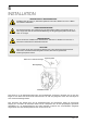
5 INSTALLATION DANGER LASER RADIATION! Always set up and install the unit so that a minimum distance of 1 m is kept between the laser light and the audience. DANGER OF OVERHEATING! The distance between the light output and the illuminated surface must be more than 0.1 m. Always ensure sufficient ventilation. The ambient temperature must always be below 45 °C. DANGER OF FIRE! When installing the device, make sure there is no highly inflammable material within a distance of min. 0.5 m.
DANGER TO LIFE! Please consider the EN 60598-2-17and the respective national standards during the installation! The installation must only be carried out by an authorized dealer! DANGER TO LIFE! Before taking into operation for the first time, the installation has to be approved by an expert! For installation in public or industrial areas, a series of safety instructions have to be followed that this manual can only give in part.
6 MAKING THE CONNECTIONS Connection to the Mains The unit uses an auto-range power supply that accepts input voltages between 100 und 240 volts and allows for powering further devices. 1 Connect the device to the mains with the power plug. Thus the unit is switched on. 2 To switch off the unit, disconnect the power plug. 3 Do not connect the unit to the mains voltage via a dimmer. For a more convenient operation, connect the unit to a mains outlet which is switchable.
7 OPERATION The built-in control panel of the unit features four operating buttons and a display which shows all operation statuses. After connecting the unit to the mains it requires a short initialization process and is then ready for operation. The display shortly indicates the firmware version followed by the last operating mode. The operating modes can be selected by means of the display and the control buttons. ► Operating Buttons MODE Selects the operating mode or returns to the initial screen.
Operation without External Control In automatic mode, 7 show programs are available that run at an adjustable speed or sound-controlled via the built-in microphone if desired. No. 0 1 2 3 4 5 6 Description Laser + color LEDs + white strobe LEDs Laser + color LEDs Laser + white strobe LEDs Color LEDs + white strobe LEDs Color LEDs Laser White strobe LEDs ► Automatic Mode 1 2 3 4 5 Press the button MENU so many times until is flashing in the display.
DMX Operation ► Setting the DMX Sarting address For operation with a controller with DMX512 protocol, the show laser is equipped with 9 control channels. To be able to operate the show laser with a DMX controller, the DMX starting address must be set for the first DMX channel. The starting address depends upon which DMX controller is being used. Please refer to the controller’s documentation.
130 – 134 135 – 139 140 – 144 145 – 149 150 – 154 155 – 159 160 – 164 165 – 209 210 – 255 Amber + white + blue Red + green + blue + amber Red + green + blue + white Blue + green + white + amber Red + green + amber + white White + red + blue + amber Red + green + blue + amber + white Automatic color change (one color) Automatic color change (two colors) DMX value Function Channel 3: Color change speed, if channel 2 is set to a value between 165 and 255 000 – 255 slow → fast DMX value Function Channel 4
8 CLEANING AND MAINTENANCE DANGER LASER RADIATION! When open, do not stare into the beam or view directly with optical instruments! DANGER TO LIFE! Disconnect from mains before starting maintenance operation! The operator has to make sure that safety-relating and machine-technical installations are inspected by an expert after every four years in the course of an acceptance test.
9 TECHNICAL SPECIFICATIONS Power supply: Power consumption: Laser classification according to EN 60825-1 : 2007: Laser modules: Wavelength: Color LEDs: Strobe LEDs: Flash rate: Beam angle: DMX channels: DMX512 connection: Sound control: Maximum ambient temperature Ta: 100-240 V AC, 50/60 Hz 40 W 2M Red 100 mW, green 50 mW Red 650 nm, green 532 nm 5 x RGBWA, 3 W each 8 x white, 1 W each 0-30 Hz 17° 9 3-pin XLR via built-in microphone 45° C Maximum housing temperature Tc: Min.
NOTES .............................................................................................................................................................................. .............................................................................................................................................................................. ..........................................................................................................................................................
.............................................................................................................................................................................. .............................................................................................................................................................................. ................................................................................................................................................................
© EUROLITE 2015 2015 Technische Änderungen und Irrtum vorbehalten. Every information is subject to change without prior notice. 00089091.DOCX Version 1.