
Technical data

DIAGNOSTICS
12
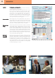
Oscilloscope
Oscilloscope with digital memory integrated in the control is
essential for accurate setting of servo drives. The signals dis-
played graphically in relation to time can be set in 4 channels
simultaneously. These can be signals of servo system, PLC IO
lines or state of internal flag bits or value of variables. Saving
starts when START button pressed is independent from fulfilling
triggering conditions. Measurement continues until available
memory for saving data is full if triggering conditions (chan-
nel, positive/negative transition) fulfilled. If data fills more than
a half of memory before fulfilling triggering condition than
saving continues until triggering point will be placed in the
middle of memory.
These settings can be saved and loaded. The inspecting part
can be searched, the selected interval could be increased,
decreased, the size of signal could be increased, decreased,
the signal could be offset vertically. The measuring results can
be saved in .xls file format to transfer them to an external com-
puter for additional analysis.
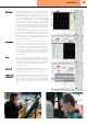
Logic analyzer
The PLC connection signals and their condition can be se-
lected by name and can be displayed in 18 analyzer chan-
nels, and they can be studied in relation to time on the control
screen. Any channel could be assigned as triggering source
either by falling or rising edge. Elapsed time from triggering
point or distance between any two moments can be meas-
ured. Measurement results can be saved in a selected file, or
measurement can be started immediately by loading any
saved configuration.
IO test
The IO lines which can be either “read/write”, or “read only”
by the PLC will be displayed in a clear table.. Some of these
are physical input and output signals between machine tool
and CNC, while others are the communication lines between
PLC and CNC. Bit setting (SET/RESET) or overwriting mem-
ory range is possible..
Symbolic IO
PLC variables can be displayed below each other in any con-
venient order. Name, address and contents of variables can
be displayed in binary or decimal representation..
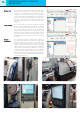
TestMes measur-
ing system test
The servo settings will always be performed by inserting the
expected parameter values in the displayed table. The re-
quired properties of the table can be selected by the softkeys
below.. The servo axes are displayed in the rows of the table,
while their properties are displayed in the columns of the
table.
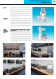
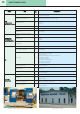
Mr. István Végh, giving technical advice to customer by phone
Mr. Tamás Pintér, chief engineer of technology of NCT, programming
a two-channel Swiss- type lathe