Euphonix System Installation Guide Document Revision: 2.6 Part Number: 840-07591-04 Release Date: August 2006 Euphonix, Inc. 220 Portage Ave. Palo Alto, California 94306 Phone: 650-855-0400 Fax: 650-855-0410 Web: http://www.euphonix.com e-mail: info@euphonix.
In the interest of continued product development, Euphonix reserves the right to make improvements in this manual and the products it describes at any time, without notice or obligation. System 5, S-5, PatchNet, eMix, EuCon, R-1, Audio Deck, Studio Hub are trademarks of Euphonix, Inc. ©2006 Euphonix, Inc. All rights reserved worldwide.
Euphonix System 5 Installation Guide Table of Contents Revision History ...................................................................................... ii List of Figures .........................................................................................................................v List of Tables ........................................................................................................................ vii Chapter 1: System 5 Overview ........................................
Euphonix System 5 Installation Guide MM641 MADI Interface Card................................................................35 SP661 Signal Processor ..........................................................................35 System 5 Console................................................................................................35 SC262 System Computer ....................................................................................37 PC254d Digital Pilot Computer ............................
Euphonix System 5 Installation Guide List of Figures 2-1 Typical Room and Equipment Layout for System 5 ........................................................20 2-2 System 5 Console ..............................................................................................................20 2-3 Console Dimensions - Top ...............................................................................................21 2-4 Console Dimensions - Side ..................................................
Euphonix System 5 Installation Guide 3-17 SH612 Studio Hub ............................................................................................................48 3-18 AM713 Front Panel ..........................................................................................................49 3-19 AM713 Rear Panel ............................................................................................................50 3-20 MA703 Front Panel ..............................................
Euphonix System 5 Installation Guide List of Tables 1-1 DF64 Requirements ...................................................................................................... 14 1-2 Summary of System 5 Components ............................................................................... 16 2-1 System 5 Components: Dimensions, Power Consumption, Heat Dissipation ............... 17 2-2 Fuse Ratings for System 5 Components ........................................................................
Euphonix System 5 Installation Guide viii
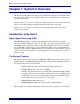
Euphonix System 5 Installation Guide Chapter 1: System 5 Overview This chapter explains the basic elements of any digital audio mixing system and introduces the components of System 5. It concludes with a section explaining how to estimate your system’s requirements. Chapter 2: Interconnecting System Components illustrates how to connect the components, where to locate them, and lists technical information about the components.
Euphonix System 5 Installation Guide System 5 Overview Inputs System 5 inputs may be mono, stereo, or any format up to 7.1, which means that a single input may use one to eight logical channels. Physical Faders Each CM408 Eight-channel Module contains eight physical faders. Each fader can control two inputs using a Swap button that switches the fader between the Swap and Main inputs. Layouts Inputs are assigned to physical faders by using Layouts.
Euphonix System 5 Installation Guide System 5 Overview Digital I/O All digital I/O is converted to and from MADI format via the DM714 AES/EBU to MADI Converter, and the MD704 MADI to AES/EBU Converter. Each unit’s main I/O handles 24 signals (12 AES/EBU pairs) and also contains an auxiliary stereo analog input or output, and an auxiliary stereo digital input or output (AES/EBU and S/PDIF). All digital inputs have built in Sample Rate Converters.
Euphonix System 5 Installation Guide System 5 Overview We recommend following these guidelines: • It is important to minimize the timing differences between signal paths to avoid cumulative timing errors. It is good system engineering practice to send sync signals to all system components from one source. • Sync signals should not be looped and each distribution amplifier should be fed directly from the master clock source. Drawings in this installation guide show the use of Word Clock.
Euphonix System 5 Installation Guide System 5 Overview Firewire Each DF64 Digital Frame requires an PC254d Digital Pilot computer. These computers require no user interaction and configure the individual DF64s on startup. Each are connected to their respective DF64s via firewire. TCC Control The PC254i Interface computer also requires no user interaction. It connects to the MC524 Monitor Interface and up to seven ML530 Mic/Line Interfaces via TCC connection.
Euphonix System 5 Installation Guide System 5 Overview Estimating System Requirements This section helps estimate the system requirements for a particular installation. Contact a Euphonix representative for an exact specification. Use following categories to determine the System 5 components necessary for your studio. Most of the studio details considered here are relevant to any digital mixing system.
Euphonix System 5 Installation Guide System 5 Overview I/O Specification When considering I/O requirements, count the number of analog and AES/EBU inputs and outputs required to hook up all equipment and auxiliary panels for extra equipment. Do not specify I/O from the console perspective. For example, it is not efficient to specify one analog input and one analog output to be used as an insert point for each channel input.
Euphonix System 5 Installation Guide System 5 Overview Table 1-2 Summary of System 5 Components Component CM401 Master Module CM402 Expanded Channel Module CM403 Powered Console Module CM408 8-channel Module CM409HTP Track Panner Module Function Number Notes These two modules make up the center section of the S5 console. 1 of each required Ethernet devices. CM401 includes a TB Mic and expansion port for TB external switches wiring.
Euphonix System 5 Installation Guide Chapter 2: Interconnecting System Components This chapter summarizes technical information for System 5’s components, including size, weight, power consumption, cooling, and fuse requirements and shows their interconnections. To plan an installation, examine Figure 2-1 to learn about suggested equipment locations. The Sync, MADI, and Control hookup diagrams (Figure 2-10 through Figure 2-13) all show maximum cable distances.
Euphonix System 5 Installation Guide Interconnecting System Components ML530 Mic/Line Interface 3.5” 89 mm 2RU 17”/432 mm (19”/483 mm faceplate) 18.5” 470 mm 17 lb 7.7 kg 100 W 345 BTU/hr SC262 System Computer 3.5” 89 mm 2RU 17”/432 mm (19”/483 mm faceplate) 22” 560 mm 23 lb 10.5 kg 200 W 685 BTU/hr PC254i Digital Pilot 3.5” 89 mm 2RU 17”/432 mm (19”/483 mm faceplate) 18.5” 470 mm 23 lb 10.5 kg 200 W 685 BTU/hr PC254d Digital Pilot 3.
Euphonix System 5 Installation Guide Interconnecting System Components Table 2-2 Fuse Ratings for System 5 Components Component How to Change Voltage Setting 100/115/120 VAC 220/230/240 VAC CM401 T5 A T5 A autoranging CM402 T5 A T5 A autoranging CM403 T5 A T5 A autoranging CM408 T5 A T5 A autoranging MC524 Monitor Interface 6A 3A autoranging ML530 Mic/line Interface 6A 3A autoranging SC262 System Computer 6A 3A autoranging PC254i Digital Pilot 6A 3A autoranging PC254d D
Euphonix System 5 Installation Guide Interconnecting System Components Typical Room and Equipment Layout for System 5 Figure 2-1 Typical Room and Equipment Layout for System 5 Typical Console Layout CM424 Producer’s Module with Writing Surface Three CM408 Eight-channel Modules CM402 and CM401 Center Section Modules CM403 Film and Three CM408 Panner Module Eight-channel Modules Figure 2-2 System 5 Console 20 CM424 Producer’s Module with Writing Surface
Euphonix System 5 Installation Guide Interconnecting System Components Console Dimensions 4.0 72.0 4.0 41.0 Figure 2-3 Console Dimensions - Top 41 30.5 39.5 29.5 24.
Euphonix System 5 Installation Guide Interconnecting System Components 1.75 2.43 120.0 9.12 9.69 24.63 60.0 100.0 1.61 3.08 2.49 29.52 11.96 33.
Euphonix System 5 Installation Guide Interconnecting System Components Suggested Rack Elevations () (*% )*+ $% $&' % ## , - ! " PC ! " PC $) $ * )*+ () (*% )*+ $% $&' % ## , - ! " % ! " %
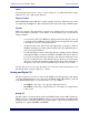
Euphonix System 5 Installation Guide 32 31 30 29 28 27 26 25 24 23 22 21 20 19 18 17 16 15 14 13 12 11 10 9 8 7 6 5 4 3 2 1 0 Interconnecting System Components Leave Open SH612 (Studio Hub) EH 224 (EuCon Hub) SH612(Studio Hub) SC262(System PC) Leave Open TT007 MIDI Interface Frame #1 PC254i (Interface Pilot) PC254d (Digital Pilot) PC254d (Digital Pilot) PC254d (Digital Pilot) Frame #2 Frame #3 Figure 2-7 Three-frame System
Euphonix System 5 Installation Guide Interconnecting System Components Audio Hookup Microphone Studi o Mic Lines 1-48 ML530 OUTPUTS INPUTS 1-12 48 Analog 48 Analog AM713 48 Analog AM713 13-24 ML530 OUTPUTS INPUTS 1-12 13-24 Mic Line Interface Analog to MADI Digital I/O AES/EBU Device Inputs 1-48 MD704 48 channels (24 AES/EBU pairs) MD704 MADI to AES/EBU AES/EBU Device Outputs 1-48 DM714 48 channels (24 AES/EBU pairs) DM714 Devices requiring format conversion 1-56 In 1-56 Out AES/
Euphonix System 5 Installation Guide Interconnecting System Components Synchronization Hookup OUTPUTS ML530 Maximum Cable Distances: Word: 165 ft (50 m) AM713 INPUTS 1-12 W/C In 13-24 OUTPUTS ML530 AM713 INPUTS 1-12 W/C In 13-24 Mic Line Interface Analog to MADI Studio House Video Word Clock Distribution Amplifier Studio Master Clock W/C In FC727 Format Converter W/C In W/C In W/C In MD704 W/C In MD704 SH612 SH612 MADI to AES/EBU Studio Hub Euphonix Euphonix Euphonix Eup
Euphonix System 5 Installation Guide Interconnecting System Components MADI Hookup Device Outputs One DF64 with 11 DSP Cards 1 2 3 4 5 6 7 Device Inputs 8 1 2 MADI Inputs SH612 MADI Outputs DF64 7 8 9 3 4 5 6 MADI Outputs MADI Inputs 9 10 11 10 MADI Inputs A B C D MADI Outputs A B C D MM-641 MADI Interface Card MA703 MADI to Analog Converter for MC524 Monitor Interface The 4th output cable from the DF64 to the SH612 on the included wiring harness is not used Device Outputs On
Euphonix System 5 Installation Guide Interconnecting System Components Device Outputs Two DF64s 1 2 3 4 5 6 7 MADI Inputs MADI Outputs 7 8 9 10 11 12 Device Inputs 8 1 SH612 2 3 MADI Inputs DF64 A B C D MADI Outputs MM-641 MADI Interface Cards MA703 MADI to Analog Converter for MC524 Monitor Interface MADI Inputs Bus Cascades A B C D MADI Outputs A B C D MM-641 MADI Interface Cards Figure 2-12 MADI hookup for two DF64 cores and one SH612 Studio Hub 28 5 9 10 11 12 MADI Inputs
Euphonix System 5 Installation Guide Interconnecting System Components Device Outputs Three DF64s 1 2 3 4 5 6 7 8 9 10 11 12 MADI Inputs SH612 #1 MADI Outputs 1 2 3 4 5 6 7 8 9 10 11 12 DF64 MADI Inputs A B C D MA703 MADI to Analog Converter for MC524 Monitor Interface MADI Outputs A B C D MM-641 MADI Interface Cards DF64 MADI Inputs A B C D MADI Outputs A B C D MM-641 MADI Interface Cards DF64 MADI Inputs A B C D Bus Cascades MADI Outputs A B C D MM-641 MADI Interface Cards
Euphonix System 5 Installation Guide Interconnecting System Components Device Outputs Four DF64s 1 2 3 4 5 6 7 8 9 10 11 12 MADI Inputs SH612 #1 MADI Outputs 1 2 3 4 5 6 7 8 9 10 11 12 DF64 MADI Inputs A B C D MA703 MADI to Analog Converter for MC524 Monitor Interface MADI Outputs A B C D MM-641 MADI Interface Cards DF64 MADI Inputs A B C D MADI Outputs A B C D MM-641 MADI Interface Cards DF64 MADI Inputs A B C D MADI Outputs A B C D MM-641 MADI Interface Cards DF64 Bus Cascad
Euphonix System 5 Installation Guide Interconnecting System Components Control Hookup ESBus Lynx Sony 9-pi n LT C Devices Studio Hub MMC MTC SH 612 RS422 CONTROL Up to six additional Mic/Line Interfaces TT007 OUTPUTS ML530 INPUTS 1-12 13-24 MIDI Port #2 Maximum Distances Mic/Line Interface MIDI I/F Euphoni x Euphoni x Euphoni x Euphoni x Euphoni x Euphoni x Euphoni x Euphoni x Euphoni x Euphoni x Euphoni x Euphoni x Euphoni x FC-631 FRAME CONTROLLE R SP-661 SIGNAL PROCESSOR SP-6
Euphonix System 5 Installation Guide Interconnecting System Components 32
Euphonix System 5 Installation Guide Chapter 3: System 5 Components This chapter discusses the System 5 components and all connectors necessary for operation. Pinouts for user-wired connections are shown for each component, along with the cables and connectors provided by Euphonix. DF64 Digital Frame The DF64 contains three types of cards: FC631 Frame Controller, MM641 MADI Interface, and SP661 Signal Processor (all three shown in Figure 3-2).
Euphonix System 5 Installation Guide System 5 Components Euphonix Euphonix Euphonix MADI Inputs AES Sync In A Out B Word Sync 75 In Out C D MADI Outputs FireWire A B Chassis ID C Sync Source DSP Activity AES Word Int D A MADI Input OK 44.
Euphonix System 5 Installation Guide System 5 Components FC631 Frame Controller AES Sync In (3-pin Lemo Female): The DF64 Digital Frame clocks to the signal at this port when the sync source is set to AES Sync. Connect this port to a digital sync reference. AES Sync Out (3-pin Lemo Male): This signal is active regardless of the selected sync source. Word In (BNC): The DF64 clocks to the signal at this port when the sync source is set to Word Clock. Connect this port to a digital sync reference.
Euphonix System 5 Installation Guide System 5 Components 1 13 25 14 Pin # 1 2 3 4 5 6 7 8 9 10 11 12 13 14 15 16 17 18 19 20 21 22 23 24 25 Signal LED 1 output (active low) Switch 1 input (active high) +5V LED 3 output (active low) Switch 3 input (active high) +5V LED 5 output (active low) Switch 5 input (active high) +5V LED 7 output (active low) Switch 7 input (active high) +5V +5V +5V LED 2 output (active low) Switch 2 input (active high) +5V LED 4 output (active low) Switch 4 input (active high) +
Euphonix System 5 Installation Guide System 5 Components SC262 System Computer I O I O POWERRESET Figure 3-5 SC262 Front and Rear Panels VGA Connector (DA-15): Main video monitor connection. Keyboard (PS/2): Main keyboard connection. Mouse (PS/2): Main trackball connection. Serial Port 1 (DE-9): Touchscreen control connection. Connect the machine room KVM extender to the VGA, keyboard, and mouse connectors on the rear panel of the SC262. A second KVM extender is located at the console.
Euphonix System 5 Installation Guide System 5 Components PC254d Digital Pilot Computer DIGITAL PILOT COMPUTER PC 254d Figure 3-6 PC254d Front and Rear Panels IEEE 1394 Ports (3 6-pin IEEE 1394 connectors): Connect any port to IEEE 1394 connector on the FC631 card in the respective DF64 via provided IEEE 1394 cables (Firewire). Network Port (RJ45): Connect to EuCon Network Switch via RJ45 (provided). Power Connectors (IEC): Accepts two standard IEC power cords (provided).
Euphonix System 5 Installation Guide System 5 Components PC254i Interface Computer INTERFACE PILOT COMPUTER PC 254i Figure 3-7 PC254i Front and Rear Panels Parallel Port (DB-25): Currently unused.. TCC Main Port (Lower DC-62HD): Connect TCC breakout cable (provided) to this port. This cable breaks out to four DB-15 connectors that provide control hookup for the MC524 Monitor Interface and three ML530 Mic/Line Interfaces.
Euphonix System 5 Installation Guide System 5 Components MC524 Monitor Interface MONITOR-COMMS INTERFACE MC 524 Figure 3-8 MC524 Front and Rear Panels Power Switch: Powers the unit off/on. In 1 (38-pin ELCO): Talk Back, Listen Back and Mic inputs. This connector receives four stereo listen channels and two stereo talk mic inputs. Signals can be boosted or attenuated. In a standard patch configuration, input cable fans out to 12 female XLRs.
Euphonix System 5 Installation Guide System 5 Components Input/Output Connections Table 3-2 In 1 Elco 38 Pinout Crk # Designator 24 X 32 High Low Gnd 1 M1 Talk 1 A E L 2 M2 Talk 2 B F M 3 M3 Listen 1 C H N 4 M4 Listen 2 D J P 5 M5 Listen 3 DD JJ PP 6 M6 Listen 4 EE KK RR 7 FF LL SS 8 HH MM TT 9 R S V 10 T U W 11 X Z AA 12 Y BB CC B A F E H J T S R Y X B B A A D D J J F F E E K K P P U W V Z K P N M L D C L L R R C C
Euphonix System 5 Installation Guide System 5 Components Table 3-3 In 2 Elco 90 Pinout High Low Gnd 1 L3 Cntrl Rm (L) A H R 2 L4 Cntrl Rm (C) B J S 3 L5 Cntrl Rm (R) C K T 4 L6 Cntrl Rm (Sl) D L U 5 L7 Cntrl Rm (Sr) E M V 6 L8 Cntrl Rm (B) F N W 7 L9 Cntrl Rm (Li) X AE AM 8 L10 Cntrl Rm (Ri) Y AF AN 9 L11 Mon A (L) Z AH AP 10 L12 Mon A (C) AA AJ AR 11 L13 Mon A (R) AB AK AS 12 L14 Mon A (Sl) AC AL AT 13 L15 Mon A (Sr) BJ BS BY
Euphonix System 5 Installation Guide System 5 Components Table 3-4 Out 1 Elco 90 Pinout Low Gnd 1 BO11 Mon A (L) A H R 2 BO12 Mon A (C) B J S 3 BO17 Mon A (R) C K T 4 BO18 Mon A (Sl) D L U 5 BO19 Mon A (Sr) E M V 6 BO20 Mon A (B) F N W 7 BO21 Mon A (Li) X AE AM 8 BO22 Mon A (Ri) Y AF AN 9 BO23 Mon B (L) Z AH AP 10 BO24 Mon B (R) AA AJ AR 11 BO25 Mon C (L) AB AK AS 12 BO26 Mon C (R) AC AL AT 13 BO27 Mon D (L) BJ BS BY 14 BO28
Euphonix System 5 Installation Guide System 5 Components Table 3-5 Out 2 Elco 90 Pinout Low Gnd 1 BO31 Solo L A H R 2 BO32 Solo R B J S 3 TL1 Talk 1 C K T 4 TL2 Talk 2 D L U 5 TL3 Listen 1 E M V 6 TL4 Listen 2 F N W 7 TL5 Listen 3 X AE AM 8 TL6 Listen 4 Y AF AN 9 BO3 CR main (L) Z AH AP 10 BO4 CR main (C) AA AJ AR 11 BO5 CR main (R) AB AK AS 12 BO6 Cntrl Rm (Sl) AC AL AT 13 BO7 Cntrl Rm (Sr) BJ BS BY 14 BO8 CR main (B) BK
Euphonix System 5 Installation Guide System 5 Components Table 3-6 Out 3 DB-25 Pinout Crk # Designator 24 X 32 High Low Gnd 1 T1 24 12 25 2 T2 10 23 11 3 L1 21 9 22 4 L2 7 20 8 5 L3 18 6 19 6 L4 4 17 5 7 Solo L 15 3 16 8 Solo R 1 14 2 13 12 11 10 9 8 7 6 5 4 3 2 1 25 24 23 22 21 20 19 18 17 16 15 14 Figure 3-13 DB-25 Connector 45
Euphonix System 5 Installation Guide System 5 Components ML530 Mic/Line Interface MIC LINE INTERFACE 1 2 3 4 5 6 7 8 9 10 11 12 13 14 15 16 17 18 19 20 21 22 23 24 ML 530 OUTPUTS ML530 INPUTS 1-12 CONTROL 13-24 VGA Figure 3-14 ML530 Front and Rear Panels Inputs (two 38-pin ELCO sockets): A total of 24 microphone inputs are received on two 38-pin ELCO connectors (connectors and pins provided).
Euphonix System 5 Installation Guide LL PP N N M M K J J H U U T T SS RR VV W W XX Y Y DD DD JJJ E E E E KKK F F F F L PPP P H H H N N N Wiring Instruction & Description + - G 1 Mic In 1 / Mic In 13 From studio Mic 1 / 13 A E L 2 Mic In 2 / Mic In 14 From studio Mic 2 / 14 B F M 3 Mic In 3 / Mic In 15 From studio Mic 3 / 15 C H N 4 Mic In 4 / Mic In 16 From studio Mic 4 / 16 D J P 5 Mic In 5 / Mic In 17 From studio Mic 5 / 17 DD JJ PP 6 Mic In 6 / Mic
Euphonix System 5 Installation Guide System 5 Components SH612 Studio Hub 96 44.1 Int ->480000 Gen ->00:00:00:00 Stop D 1 2 3 Locked 612 I 4 AES WORD INTERNAL VIDEO SYNC VIDEO SH OTHER TC LOCK 6 Info 0 11 Escape Select 12 WORD VID-SYNC VIDEO IEEE1394 Figure 3-17 SH612 Studio Hub Video In (BNC): Accepts signal from house blackburst or composite sync. AES Sync In (female XLR): Accepts signal from a digital sync reference.
Euphonix System 5 Installation Guide System 5 Components AM713 Analog to MADI Converter Front Panel Figure 3-18 AM713 Front Panel Signal Strength LEDs: Each of the 28 channels has a four-segment LED that represents the following signal levels: -42 dB, -18 dB, -6 dB (green), -0.05 dB (red). Trim Pots Access: Three trim pots adjust the maximum analog input level of channels 1– 8, 9–16, and 17–24 in 2-dB steps between +12 and +26 dBu.
Euphonix System 5 Installation Guide System 5 Components Rear Panel Figure 3-19 AM713 Rear Panel Input Voltage Selector: This red switch allows operation in either 100/110/115 VAC or 220/230/240 VAC environments. A fuse must also be changed for 220/230/240 VAC operation. Units are shipped set and fused for 100/110/115 VAC. Power Connector (IEC) and Fuse Tray: The IEC power connector accepts standard IEC power cords. The fuse tray contains both the active fuse and a spare for 220/230/240 VAC operation.
Euphonix System 5 Installation Guide System 5 Components MADI Out (BNC): Outputs the digital audio signal. • 1–24: Analog inputs • 25–26: Aux analog inputs • 27–28: Aux digital inputs NOTE: 28 channels are always transmitted; dual channels are not used. Trim Pots: Four detented trim pots, accessed from the front panel, adjust the analog input level of channels 1–8, 9–16, 17–24, and auxiliary analog in 3 dB steps between +6 and +27 dBU.
Euphonix System 5 Installation Guide System 5 Components MA703 MADI to Analog Converter Front Panel Figure 3-20 MA703 Front Panel Signal Strength LEDs: Each of the 28 channels has a four-segment LED that represents the following signal levels: -42 dB, -18 dB, -6 dB (green), -0.05 dB (red). Trim Pots Access: Three trim pots adjust the maximum analog output level of channels 1– 8, 9–16, and 17–24 in 2-dB steps between +12 and +26 dBu.
Euphonix System 5 Installation Guide System 5 Components Rear Panel Figure 3-21 MA703 Rear Panel Input Voltage Selector: This red switch allows operation in either 100/110/115 VAC or 220/230/240 VAC environments. A fuse must also be changed for 220/230/240 VAC operation. Units are shipped set and fused for 100/110/115 VAC. Power Connector (IEC) and Fuse Tray: The IEC power connector accepts standard IEC power cords. The fuse tray contains both the active and spare fuses.
Euphonix System 5 Installation Guide System 5 Components MADI In (BNC): Digital audio signal input. • 1–24: analog outputs • 25–26: aux analog outputs • 27–28: aux digital outputs.
Euphonix System 5 Installation Guide System 5 Components DM714 AES/EBU to MADI Converter Front Panel Figure 3-22 DM714 Front Panel Signal Strength LEDs: Each of the 28 channels has a four-segment LED that represents the following signal levels: -42 dB, -18 dB, -6 dB (green), -.05 dB (red). Trim Pot: A trim pot adjusts the analog output level of channels A1 and A2 between +12 and +26 dBu in 2-dB steps.
Euphonix System 5 Installation Guide System 5 Components Manual Selection Buttons: The button below each Sample Rate LED row manually selects the Sample Rate Source. The DM714 also allows manual selection of the Sample Rate. Power Switch: On/Off switch. Rear Panel Figure 3-23 DM714 Rear Panel Input Voltage Selector: This red switch allows operation in either 100/110/115 VAC or 220/230/240 VAC environments. A fuse must also be changed for 220/230/240 VAC operation.
Euphonix System 5 Installation Guide System 5 Components Word Out (BNC): Outputs a Word clock signal synchronized to the Sample Rate Source. In the presence of an external Word clock input, this connector provides a regenerated version of that input signal. Without an external sample rate source, this connector outputs the internally generated clock signal. MADI Out (BNC): Outputs the digital audio signal.
Euphonix System 5 Installation Guide System 5 Components MD704 MADI to AES/EBU Converter Front Panel Figure 3-25 MD704 Front Panel Signal Strength LEDs: Each of the 28 channels has a four-segment LED that represents the following signal levels: -42 dB, -18 dB, -6 dB (green), -.05 dB (red). Trim Pot: A trim pot adjusts the analog output level of channels A1 and A2 between +12 and +26 dBu in 2-dB steps. Sample Rate LEDs: These LEDs indicate the Sample Rate to which the converter is currently locked.
Euphonix System 5 Installation Guide System 5 Components Rear Panel Figure 3-26 MD704 Rear Panel Input Voltage Selector: This red switch allows operation in either 100/110/115 VAC or 220/230/240 VAC environments. A fuse must also be changed for 220/230/240 VAC operation. Units are shipped set and fused for 100/110/115 VAC. Power Connector (IEC) and Fuse Tray: The IEC power connector accepts standard IEC power cords. The fuse tray contains both the active and spare fuses.
Euphonix System 5 Installation Guide System 5 Components MADI In (BNC): Digital audio signal input. • 1–24: main digital outputs • 25–26: aux analog outputs • 27–28: aux digital outputs Bit-Depth Reduction: Sets the resolution to 16, 20, or 24 bits for the main AES/EBU channels.
Euphonix System 5 Installation Guide System 5 Components FC726 Format Converter AES 49-56 CAUTION: To prevent risk of fire replace fuse with the same type and rating, FMT A FMT B AES STEREO AES 41-48 AES 33-40 AES 25-32 AES 17-24 AES 9-16 AES 1-8 AES MONO FMT A AES/FMT B/FMT A SERVICE FC726 EUPHONIX, INC. CH 9-16 CH 49-56 IN SDIF-2 SYNC OUT IN SLAVE CLK CH 33-40 CH 25-32 FORMAT A OUT SLAVE CLK WORD SYNC AES SYNC or CURRENT FUSE 1.0-0.5A 2.
Euphonix System 5 Installation Guide System 5 Components SDIF-2 or Slave Clock In (BNC): This connector can receive either an SDIF or Slave Clock Sync signal (the FC726 automatically detects the signal type). An SDIF device must send a Word Sync signal to this connector to interface properly. Slave Clock is a sync signal (commonly implemented in Pro Tools systems and referred to as a super-clock) that runs at 256 times the sample rate. Cable not provided.
Euphonix System 5 Installation Guide System 5 Components Table 3-7 AES/EBU DB-25 Pinout Pin Description Pin 1 Pin 2 N/C Channel 1 / 2 In (COLD) Pin 3 Channel 3 / 4 In (GND) Pin 4 Channel 3 / 4 In (HOT) Pin 5 Channel 5 / 6 In (COLD) Pin 6 Channel 7 / 8 In (GND) Pin 7 Channel 7 / 8 In (HOT) Pin 8 Channel 1 / 2 Out (COLD) Pin 9 Channel 3 / 4 Out (GND) Pin 10 Channel 3 / 4 Out (HOT) Pin 11 Channel 5 / 6 Out (COLD) Pin 12 Channel 7 / 8 Out (GND) Pin 13 Channel 7 / 8 Out (HOT) Pin 14
Euphonix System 5 Installation Guide System 5 Components Table 3-8 Common DD-50 Connector Pinout and Usage With Third-party Devices Pin # 1 2 3 4 5 6 7 8 9 10 11 12 13 14 15 16 17 18 19 20 21 22 23 24 25 26 27 28 29 30 31 32 33 34 35 36 37 38 39 40 41 42 43 44 45 46 47 48 49 50 Common Connector (DB50 Female) In 1+ In 1In 2+ In 2In 3+ In 3In 4+ In 4GND In 5+/GP In A In 5In 6+/GP In B In 6In 7+/GP In C In 7In 8+/GP In D In 8Cable ID2 Cable ID1 Cable ID0 Bit Clk In+ Bit Clk InGND Word Clk In+ Word Clk InOut
Euphonix System 5 Installation Guide System 5 Components Table 3-9 FC726 TDIF Cable Wiring Specification Connector Pin Connection J1 1 NC J1 2 J2-1 J1 3 NC J1 4 J2-2 J1 5 NC J1 6 J2-3 J1 7 NC J1 8 J2-4 J1 9 J2-7,24,25 J1 10 NC J1 11 NC J1 12 NC J1 13 NC J1 14 NC J1 15 NC J1 16 NC J1 17 NC J1 18 J1-23 J1 19 NC J1 20 J1-23 J1 21 NC J1 22 NC J1 23 J2-17,J1-18,J1-20 J1 24 J2-5 J1 25 NC J1 26 NC J1 27 J2-13 J1 28 NC J1 29 J2-12 J1 30 NC J1 31 J2-11 J1 32 NC J1 33 J2-10 J1 34 J2-8 J1 35 NC J1 36 J2-20 J1 37 NC
Euphonix System 5 Installation Guide System 5 Components Table 3-10 FC726 Pro Tools Cable Wiring Specification Connector Pin Connection J1 1 J2-17 J1 2 J2-42 J1 3 J2-16 J1 4 J2-41 J1 5 J2-1 J1 6 J2-26 J1 7 J2-18 J1 8 J2-43 J1 9 J2-2 J1 10 J2-5 J1 11 J2-30 J1 12 J2-3 J1 13 J2-28 J1 14 J2-21 J1 15 J2-46 J1 16 J2-23 J1 17 J2-48 J1 18 NC J1 19 J1-23 J1 20 NC J1 21 J2-19 J1 22 J2-44 J1 23 J1-19,J2-13 J1 24 J2-11 J1 25 J2-36 J1 26 J2-7 J1 27 J2-32 J1 28 J2-8 J1 29 J2-33 J1 30 J2-25 J1 31 J2-50 J1 32 J2-24 J1 33
Euphonix System 5 Installation Guide System 5 Components Table 3-11 FC726 SDIF Cable Wiring Specification Connector Pin Connection J1 1 J4-2 J1 2 J4-1 J1 3 J4-6 J1 4 J4-5 J1 5 J4-10 J1 6 J4-9 J1 7 J4-14 J1 8 J4-13 J1 9 NC (GND) J1 10 J4-4 J1 11 J4-3 J1 12 J4-8 J1 13 J4-7 J1 14 J4-12 J1 15 J4-11 J1 16 J4-16 J1 17 J4-15 J1 18 J1-23 J1 19 J1-23 J1 20 NC J1 21 NC J1 22 NC J1 23 J1-18,19 J1 24 NC J1 25 NC J1 26 J5-2 J1 27 J5-1 J1 28 J5-6 J1 29 J5-5 J1 30 J5-10 J1 31 J5-9 J1 32 J5-14 J1 33 J5-13 J1 34 J5-4 J1 3
Euphonix System 5 Installation Guide System 5 Components GP132 1 2 MIDI 3 MMC 4 N.O. 5 C.C.
Euphonix System 5 Installation Guide System 5 Components MIDI Connections Connect the GP132’s MIDI ports to Port 2 (In and Out) on the console’s MIDI Interface. Up to four GP132s can be connected (ins and outs) to ports 2–5.
Euphonix System 5 Installation Guide System 5 Components Table 3-13 GP132 Inputs RT1 RT2 RT3 RT4 PIN 1 9 17 25 1 2 10 18 26 15 3 11 19 27 4 4 12 20 28 18 5 13 21 29 7 6 14 22 30 21 7 15 23 31 10 8 16 24 32 24 Common Common Common Common 3,6,9,12,14, 17,20,23 WARNING: If power fails on the GP132, none of the relays will function. After restoring power, the GP132 resets ALL relays.
Euphonix System 5 Installation Guide System 5 Components TT007 Setup Connect the IEC power cable (included) to your studio power. Then connect MIDI Port 2 In and Out on the TT007 to MIDI Port 1 In and Out on the System 5 MIDI Interface. Capabilities The TT007 is an optional rack-mount device that provides machine control for all Euphonix consoles. The TT007 allows the console to become the single, centralized machine control hub within any studio.
Euphonix System 5 Installation Guide System 5 Components Using the TT007 The TT007’s front panel is very easy to master. Dedicated Port buttons instantly access individual assignments for each machine control Port. Any Port can be defined as a master, controller, or slave. A single master acts as the synchronization source for all machines in the network.
Euphonix System 5 Installation Guide Index Index I Inputs 10 K A KVM Extender 12 Analog I/O 10 Audio Hookup 25 L C Layouts 10 CM401 9 CM402 9 CM403 9 CM408 9 CM409F 9 Console Dimensions 21 Console Layout 20 Converters AM713 Analog to MADI 49 DM714 AES/EBU to MADI 55 FC726 61 MA703 MADI to Analog 52 MD704 MADI to AES/EBU 58 M D R DF64 Digital Frame 14 Digital I/O 11 Digital Sync 11 Rack Elevations 23 Machine Control 13 MC524 Monitor Interface 40 Mic Inputs 11 ML530 Mic/Line Interface 46 MM64
Euphonix System 5 Installation Guide Index 74