
Troubleshooting guide
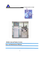


MOBILE ANORAD GANTRY SYSTEM
- 5 -
List of Tables:
Table 1: Dedicated features
Table 2: Connector Types
Table 3: Main Power Connection Pinout
Table 4: Auxiliary Power Connection Pinout
Table 5: 9 Pin D_Type Male Connector Pinout
Table 6: X Axis 9 Pin D_Type Male Connector Pinout
Table 7: Y Axis 9 Pin D_Type Male Connector Pinout
Table 8: 15 Pin D_Type Female Connector Pinout
Table 9: X Axis 15 Pin D_Type Female Connector Pinout
Table 10: Y Axis 15 Pin D_Type Female Connector Pinout
Table 11: 9 Pin D_Type Female Connector Pinout
Table 12: X Axis 9 Pin D_Type Female Connector Pinout
Table 13: Y Axis 9 Pin D_Type Female Connector Pinout
Table 14: Comm. 1 - 9 Pin D_Type Female Connector Pinout
Table 15: 1 or 3x230VAC Types Power Ratings
Table 16: Main Power Supply Ratings
Table 17: Auxiliary Power Supply Ratings
Table 18: Analog I/O Ratings
Table 19: Encoder and Hall Effect Ratings
Table 20: 24V Power Supply ( for enabling X and Y axis )
Table 21: Relay Circuit ( for enabling X and Y axis )
Table 22: Emergency Stop switch
Table 23: Power Connections
Table 24: Wiring connections of the PIC 15/200
Table 25: Status Indication of the PIC 15/200 for troubleshooting
Table 26: DIP Switches settings of the PIC Starter
Table 27: LED Indications of the PIC Starter for troubleshooting
Table 28: Analog Connector (P1)
Table 29: Digital Connector (P2)
Table 30: Incremental Encoder/Digital Connector (P3)