
Troubleshooting guide


MOBILE ANORAD GANTRY SYSTEM
- 44 -
If the Plug and Play feature has been used when installing the DS1103 PPC Controller
Board, the board has been configured automatically. No further configuration is
necessary. When starting the Hardware Navigator of ControlDesk, the DS1103 is
displayed in the Navigator in the top left of the main window. The system is ready to run
real-time applications on the board.
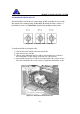
To view the board properties
1) In the Navigator, double-click the appropriate DS1103 board.
2) In the Controller Board Properties dialog box, check the individual tabs.
Figure 23: The DS1103 Controller Board Properties Dialog Box
4.3 Connector Pinouts of the DS1103
The connectors on the DS1103 PPC Controller Board are described below.
1) The Analog Connector (P1) is the 100-pin connector on the DS1103 board itself.
2) The Digital Connector (P2) is connected to the 100-pin connector on the bracket
next to P1.
3) The Incremental Encoder/Digital Connector (P3) is connected to the 100-pin
connector on the bracket next to P2.