
Troubleshooting guide


MOBILE ANORAD GANTRY SYSTEM
- 4 -
List of Figures:
Figure 1: Dedicated I/O
Figure 2: Panel Layout
Figure 3: Motor Power Connection
Figure 4: Power Terminal Connections
Figure 5: SAX-5/230 Servo Amplifier Relay Circuit
Figure 6: Encoder / Hall sensor Pin Assignment
Figure 7: Analog input with single-ended source
Figure 8: RS232 Interface
Figure 9: PIC 15/200 Connectors Location
Figure 10: Block Diagram of the PIC 15/200
Figure 11: Detail Block Diagram of the PIC 15/200
Figure 12: Wiring connections of the PIC 15/200
Figure 13: Location of the Z-axis COM 3 connector
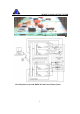
Figure 14: Wiring of the Z-axis Motor
Figure 15: Actual wiring of the Z-axis Motor
Figure 16: Circuit Diagram of the AOK, SO1, SO2 and SO3 LEDs
Figure 17: The dSPACE DS1103 PPC controller board
Figure 18: The ROBO-678 single board computer
Figure 19: DS1103 and ROBO-678 in the DAQCON Industrial Pentium III Computer
Figure 20: The DS1103 Address Switches
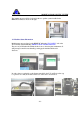
Figure 21: The DS1103 board in host PC
Figure 22: The ControlDesk Screen
Figure 23: The DS1103 Controller Board Properties Dialog Box
Figure 24: The SUB-D Connector and DS1103 board