
Troubleshooting guide


MOBILE ANORAD GANTRY SYSTEM
- 36 -
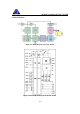
Z Axis
Driver Pin #
Signal
Connected to
3 CMRET
Pin 36 of the J5 connector
6 CREF+
Pin 35 of the J5 connector
7 CREF-
Pin 36 of the J5 connector
8 +VCC
Pin 29 of the J5 connector
9 VCCRET
Pin 27 of the J5 connector
-- +5V
Pin 1 of the Z axis COM 3 connector
-- Ha
Pin 7 of the Z axis COM 3 connector
-- HARET
Pin 6 of the Z axis COM 3 connector
-- Hb
Pin 2 of the Z axis COM 3 connector
-- Hc
Pin 3 of the Z axis COM 3 connector
Table 24: Wiring conne ctions of the PIC 15/200
Figure 14: Wiring of the Z-axis Motor